Refrigeration apparatus

A refrigeration device and freezer technology, which is applied in the direction of refrigerators, refrigeration components, refrigeration and liquefaction, etc., can solve the problems that refrigeration devices cannot improve efficiency and cannot perform heat transfer, etc., and achieve easy rotation speed control and increase refrigeration effect , Realize the effect of evaporator structure and/or condenser structure

Inactive Publication Date: 2009-02-18
EBARA CORP
View PDF0 Cites 2 Cited by
  • Summary
  • Abstract
  • Description
  • Claims
  • Application Information

AI Technical Summary

Problems solved by technology

[0004] But on the other hand, there is the following problem in the refrigerating apparatus of the above-mentioned prior art: at the time of partial load (when the number of units is controlled), the evaporators 201-1, 201-2 and the condensation of the refrigerating machines 200-1, 200-2 stopped The devices 205-1, 205-2 are stopped, so they cannot play the role of heat transfer, and the refrigeration unit cannot improve efficiency at part load

Method used


Image

  • Refrigeration apparatus
  • Refrigeration apparatus
  • Refrigeration apparatus

Examples


Embodiment Construction

[0036] Hereinafter, embodiments of the present invention will be described in detail with reference to the drawings.

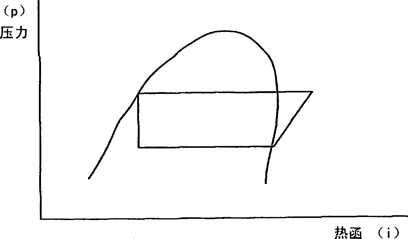
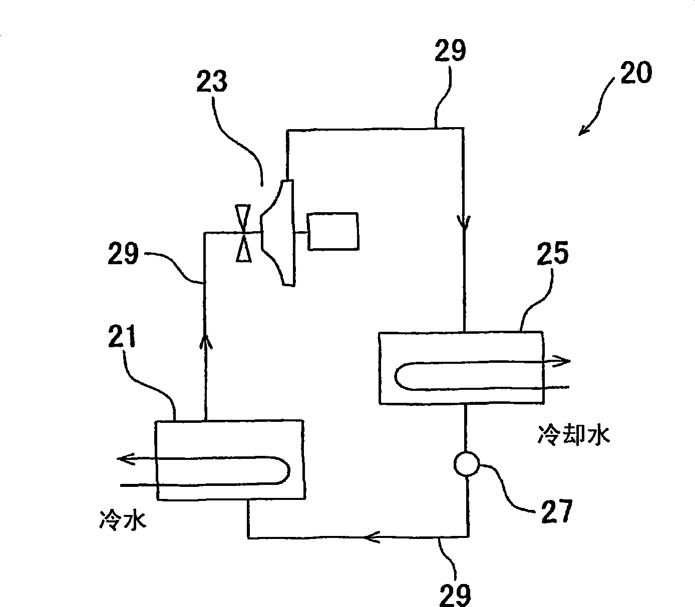
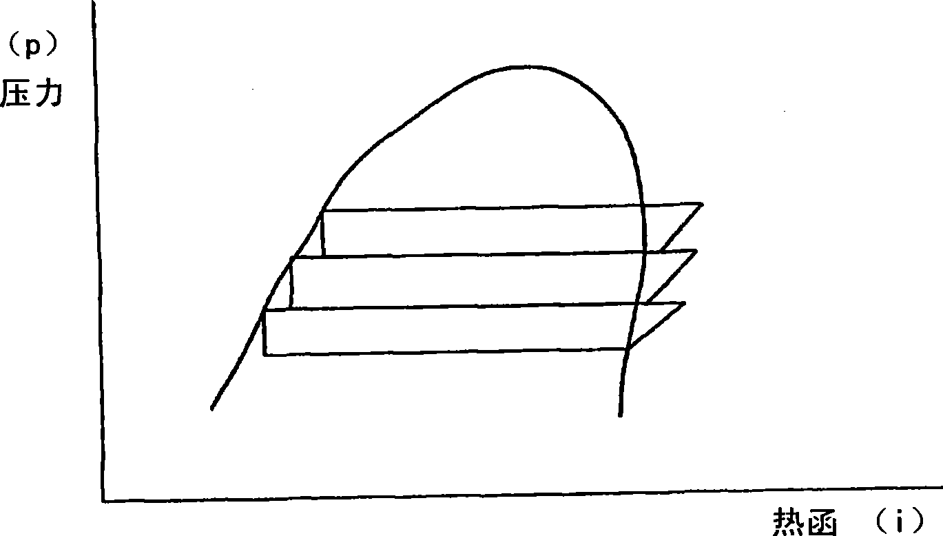
[0037] Since the refrigerating machine of the present invention is composed of a plurality of refrigerating machines (compression refrigerating machines performing a vapor compression refrigeration cycle), a specific example of a single refrigerating machine used in the present invention will be described in advance. figure 2 , Figure 4 and Figure 6 All are structural diagrams showing refrigerators 20, 20A, and 20B that can be used in the refrigerator of the present invention, figure 1 , image 3 and Figure 5 These are diagrams showing refrigeration cycles of the refrigerators 20 , 20A, and 20B, respectively. figure 2 The refrigerator 20 shown is constituted by a closed system in which a refrigerant is enclosed. Specifically, the evaporator 21 that absorbs heat from cold water (fluid to be cooled) to evaporate the refrigerant to exert a cooling effec...


PUM


Abstract

The invention relates to a cooling apparatus having multiple refrigeration units (20-1, 20-2) each including evaporator (21-1, 21-2) structured to deprive cold water of heat and cause a refrigerant to evaporate, thereby exerting refrigerating effect; compressor (23-1, 23-2) for compressing of refrigerant vapor into high-pressure vapor; and condenser (25-1, 25-2) for cooling of the high-pressure vapor with cooling water to thereby achieve condensation. The cold water is connected in series with the evaporators (21-1,21-2) of the multiple refrigeration units (20-1, 20-2), and is sequentially cooled by the heat of evaporation of the refrigerant of the multiple evaporators (21-1, 21-2). The cooling water is connected in series with the condensers (25-1, 25-2) of the multiple refrigeration units (20-1, 20-2), and sequentially cools the refrigerant of the multiple condensers (25-1, 25-2).

Description

technical field [0001] The present invention relates to a refrigerating device in which a cooling fluid (cooling source such as cooling water, cooling air, etc.) uses a fluid that undergoes a sensible heat change, and a fluid to be cooled uses a fluid that undergoes a sensible heat change such as cold water or salt water. freezer. Background technique [0002] Conventionally, there is a refrigerating apparatus including a plurality of refrigerating machines including an evaporator, a compressor, and a condenser (for example, refer to Japanese Laid-Open Patent Publication No. 2003-130428). Fig. 19 is a structural diagram showing an example of such a refrigeration device, Figure 20 It is a figure which shows the supply state of cold water and cooling water in this refrigeration apparatus. The freezing device shown in the two figures has two refrigerators 200-1, 200-2, which are respectively connected to evaporators 201-1, 201-2, compressors 203-1, 203 by refrigerant pipes 20...

Claims


Application Information

Patent Timeline
IPC IPC(8): F25B1/00F25B11/02
CPCF25B2400/13F25B9/06F25B2400/06F25B1/00
Inventor 井上修行
Owner EBARA CORP
Why Eureka
Try Eureka