Laser-induced microparticle jetting ignition method

A laser-induced, particle-based technology, applied in the direction of engine ignition, engine components, machines/engines, etc., can solve the problems of unfavorable engine continuous ignition work, large heating area, long ignition delay time, etc., to achieve convenient and high-frequency continuous ignition The possibility of overcoming the effect of large heating area

Inactive Publication Date: 2009-02-11
INST OF MECHANICS - CHINESE ACAD OF SCI
View PDF0 Cites 16 Cited by
  • Summary
  • Abstract
  • Description
  • Claims
  • Application Information

AI Technical Summary

Problems solved by technology

The disadvantage of this ignition method is that there is no intermediate process to transfer the laser energy to the combustible mixture, but the non-resonant absorption of the laser energy by the combustibl

Method used


Image

  • Laser-induced microparticle jetting ignition method
  • Laser-induced microparticle jetting ignition method

Examples


Embodiment Construction

[0020] figure 1 The experimental device shown includes a laser 1 and a combustion chamber body. The combustion chamber body is provided with a combustion chamber 6 and an explosion-proof section 8. An aluminum explosion-proof film 7 is arranged between the combustion chamber 6 and the explosion-proof section 8. On the front wall of the combustion chamber 6 A focusing lens 2 matching the laser 1 is provided, a detection window 3 and three pressure sensors 4 are provided on the side wall of the combustion chamber 6, and an absorption target 5 is provided at the focal point of the focusing lens in the combustion chamber 6.

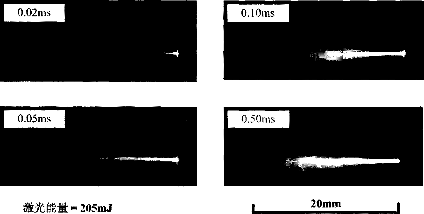
[0021] When using the above-mentioned experimental device to conduct experiments, the mixture of gaseous or liquid atomized hydrocarbon fuel and oxygen or air is placed in the combustion chamber 6 in advance, and the laser pulse emitted by the laser 1 is irradiated into the combustion chamber 6 through the focusing lens 2 and focused To the surface of the abs...


PUM


Abstract

The invention discloses a laser-induced particle jet ignition method; the method is as follows: laser pulses are led into a combustion chamber of an engine through a focusing lens in a common way; the focal position of the focusing lens in the combustion chamber is provided with an absorbing target; the hot particle jet which is generated after the absorbing target is intensively heated by laser is used for starting the combustion or the detonation of flammable mixture in the combustion chamber. The laser ignition method of the invention avoids the use of high-power laser, and increases the convenience for selecting ignition positions and the probability of high-frequency continuous ignition. In addition, the ignition mode is suitable for the ignition of different types of engines.

Description

technical field [0001] The present invention relates to a method for igniting a mixture of hydrocarbon fuel and oxygen or air to combustion or detonation using a laser-induced jet of particles. Background technique [0002] For engines using spark plug ignition, although increasing the ignition voltage of the spark plug can increase the ignition speed, improve the combustion efficiency of the combustible mixture, and improve the power performance of the engine, the ignition voltage of the existing engine spark plug has reached 20-50KV. If it is further increased The ignition voltage and ignition energy will not only make the structure of the ignition system more complicated, but also greatly reduce the reliability of the ignition system, which will affect the normal operation of the engine. [0003] For this reason, in terms of engine ignition, laser ignition has attracted people's attention as a particularly active and valuable method. [0004] The current laser ignition m...

Claims


Application Information

Patent Timeline
IPC IPC(8): F02P23/04
Inventor 杨乾锁彭志敏刘春竺乃宜
Owner INST OF MECHANICS - CHINESE ACAD OF SCI
Why Eureka
Try Eureka