Deep-drawing processing device
A technology of deep processing and mounting table, which is applied in the improvement field of retrograde mechanism, can solve problems such as taking a long time and costing more trouble, and achieve the effect of reducing replacement work, simplifying structure and reducing replacement frequency
- Summary
- Abstract
- Description
- Claims
- Application Information
AI Technical Summary
Problems solved by technology
Method used
Image
Examples
Embodiment 1
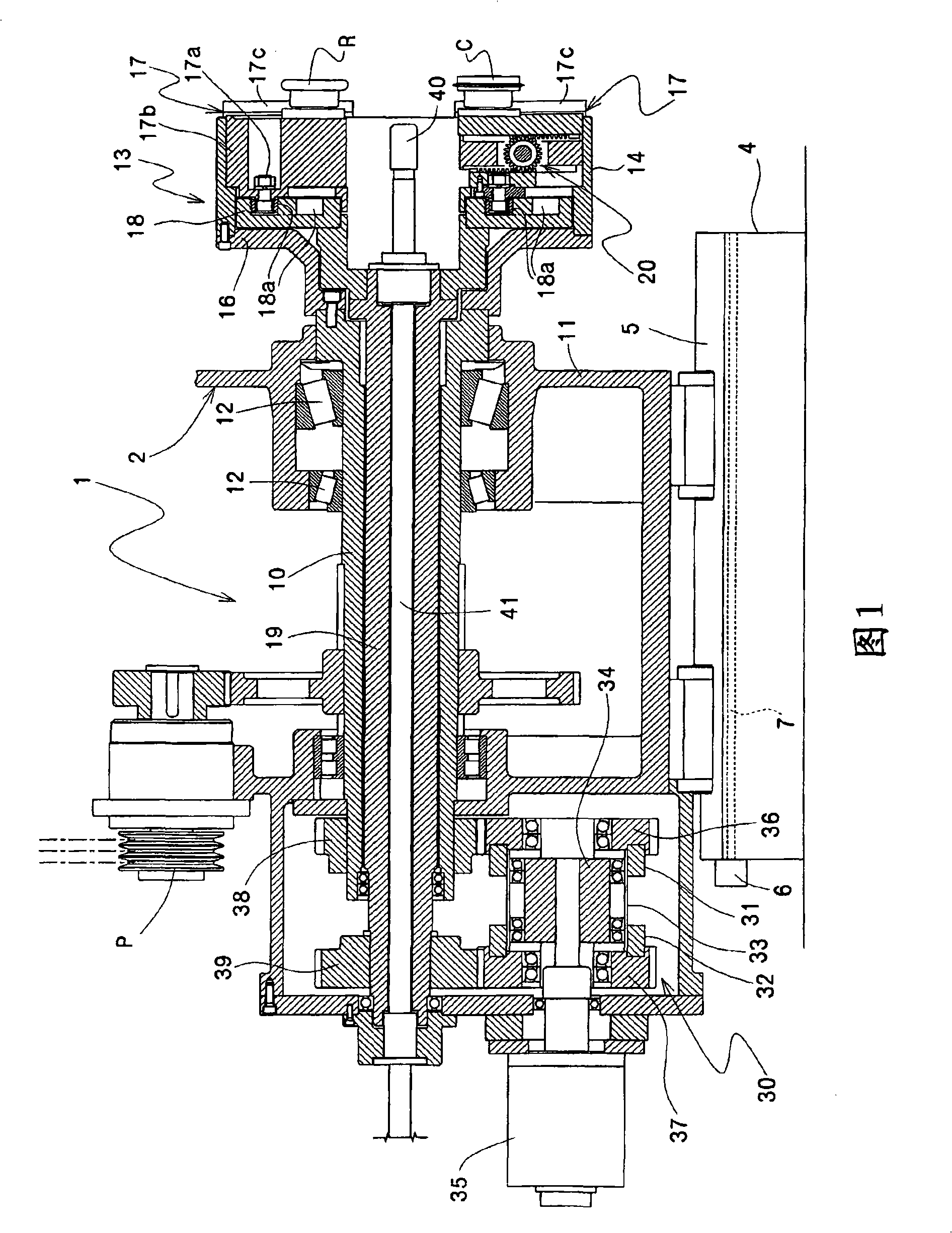
[0060] Figure 1-7 An example of the drawing processing apparatus of the present invention is shown.
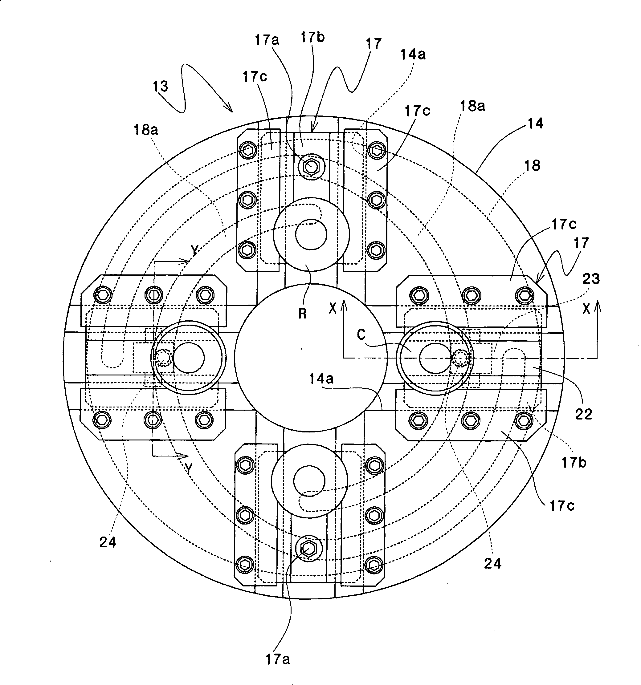
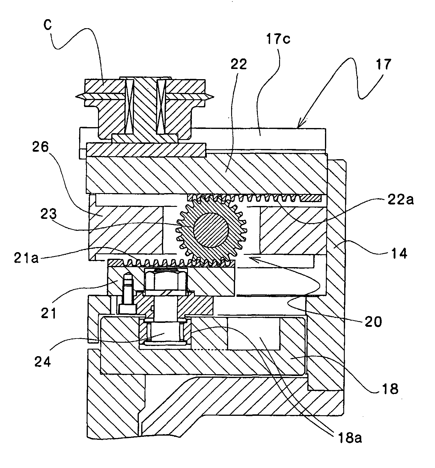
[0061] This drawing processing device 1 is the same as the conventional example. At the front end of the main shaft 10, there is a roll mounting table 13 that supports the drawing roll R and the cutting roll C so as to be slidable in the radial direction. The front end of the camshaft 19 has a cam plate 18 that moves the above-mentioned drawing roller in the radial direction. After drawing the tip of the tube, the cutting roll C cuts off the remaining portion of the tip of the tube to be processed which has been reduced in diameter.
[0062] The number of arrangement of the drawing roll R and the cutting roll C is not particularly limited. In this embodiment, such as figure 2 As shown, an example in which two drawing rolls R and a cutting roll C are respectively arranged at opposing positions is shown.
[0063] Then, the guide pins 17a and 24 of the drawing roll R on the ...
Embodiment 2
[0076] Figure 8 ~ Figure 14 Another example using the drawing processing apparatus of this invention is shown.
[0077]In this drawing processing apparatus 1A, when drawing a cylindrical blank with a thin wall or a cylindrical blank with a large diameter, the processing part (tip portion) of the cylindrical blank does not move until it moves along the mandrel. It is constructed so that it deforms abnormally inside due to the pressing force of the drawing roll, and the front end of the main shaft 10 has a roll mounting table 13 that slidably supports the drawing roll R, and at the same time moves the drawing roll R in the radial direction. , the drawing processing device for shrinking the front end of the fixed cylindrical blank. Moving backup rollers 60 .
[0078] The number of arrangement of the drawing roll R and the cutting roll C is not particularly limited. In this embodiment, such as Figure 9 As shown, two drawing rolls R and cutting rolls C are respectively arrange...
Embodiment 3
[0095] Figure 15 ~ Figure 20 Another example using the drawing processing apparatus of this invention is shown.
[0096] This drawing processing device 1B can perform the process of removing the burr inside the cut surface generated when the unnecessary part of the end portion is cut by the cutting roll in a continuous process with the drawing process and the cutting process. A drawing processing device that supports the roll mounting table 13 of the drawing roll R movably in the radial direction, and simultaneously moves the drawing roll R in the radial direction to shrink the front end of a fixedly installed cylindrical billet A chamfering tool 70 that moves in the radial direction of the main shaft 10 to finish the end of the formed blank is disposed on the roller mount 13 . In addition, in the case of a thin-walled or large-diameter cylindrical billet to be processed, on the roller mounting table 13, such as Figure 16 As shown, at a position facing the chamfering tool ...
PUM
 Abstract
Description
Claims
Application Information
 - R&D
- Intellectual Property
- Life Sciences
- Materials
- Tech Scout
- Unparalleled Data Quality
- Higher Quality Content
- 60% Fewer Hallucinations
Browse by: Latest US Patents, China's latest patents, Technical Efficacy Thesaurus, Application Domain, Technology Topic, Popular Technical Reports.
© 2025 PatSnap. All rights reserved.Legal|Privacy policy|Modern Slavery Act Transparency Statement|Sitemap|About US| Contact US: help@patsnap.com


