Artificial heart blood-pump capable of increasing blood pressure step by step
An artificial heart and blood pump technology, applied in the field of biomedical engineering, can solve problems such as blood pressure and pressure difference, and achieve the effect of reducing resistance and avoiding damage
Inactive Publication Date: 2010-11-10
BEIJING UNIV OF TECH
View PDF2 Cites 6 Cited by
- Summary
- Abstract
- Description
- Claims
- Application Information
AI Technical Summary
Problems solved by technology
The purpose of the present invention is to provide a two-stage artificial heart blood pump to solve the problem of insufficient blood pressure difference under the premise of ensuring that the red blood cells are not destroyed
Method used
View moreImage
Smart ImageViewing Examples
Examples
Embodiment Construction
Login to View More PUM
 Abstract
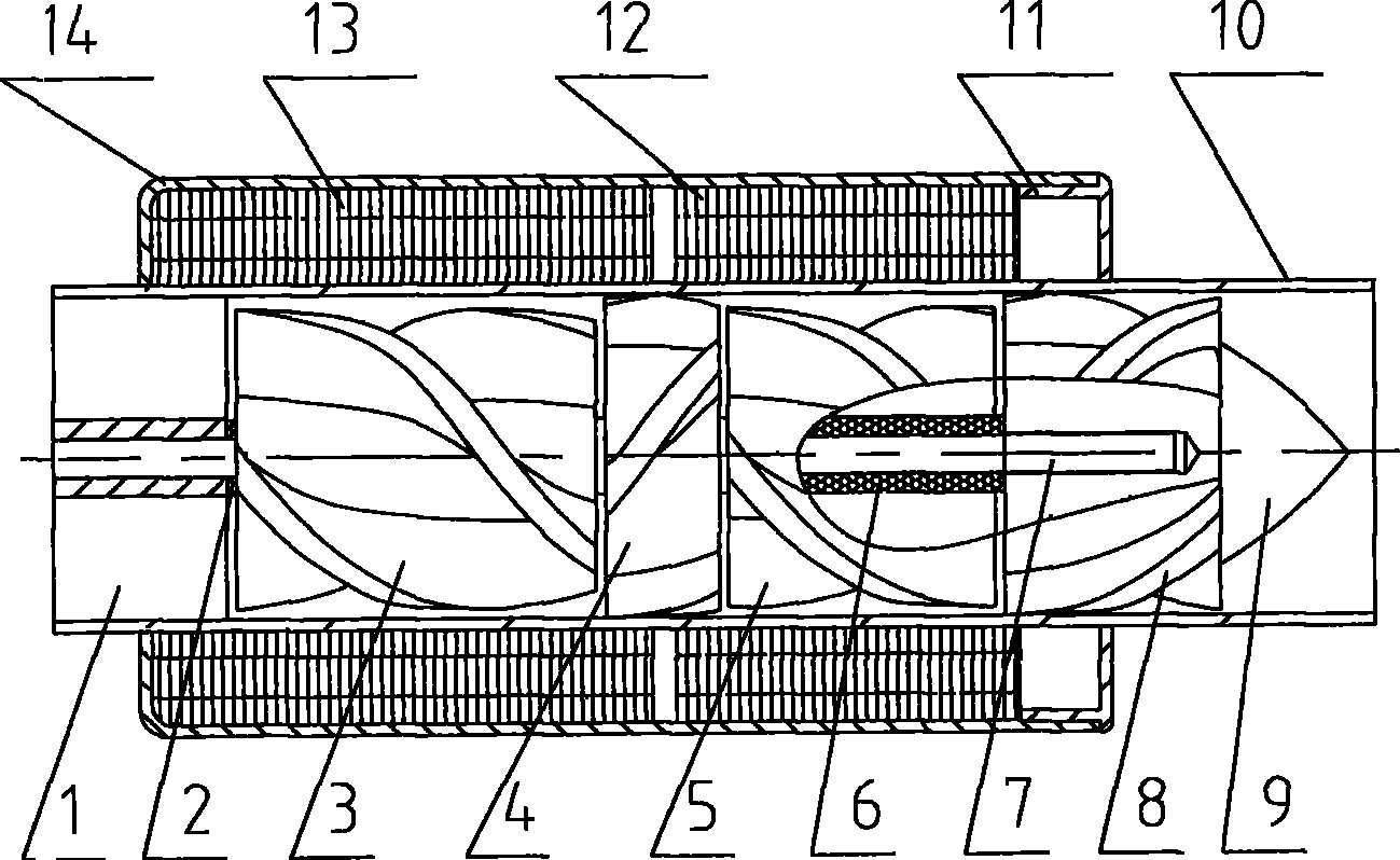
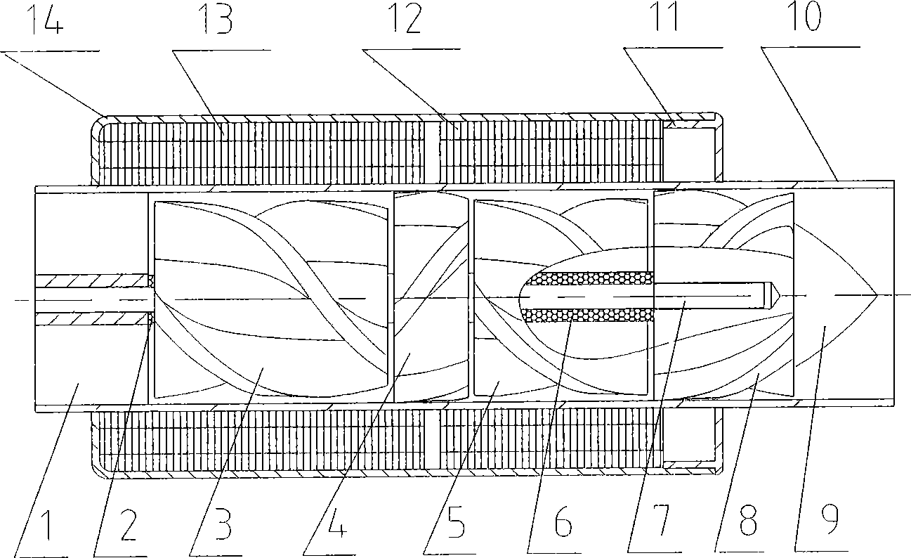
The invention discloses a mechanical heart blood pump which boosts blood pressure steps by steps, pertaining to the technical field of biomedical engineering, relating to a mechanical heart blood pump for boosting blood pressure. The mechanical heart blood pump comprises a driving stator and a rotor; a controller connected with a driving stator provides a driving power source; the driving stator composed of annular coils is located in an interlayer composed of a cylindrical shell 13 and a tubular cavity 10; a supporting rotor comprises a head guide vane 1 and a tail guide vane 8; the head guide vane 1 is arranged in the front end of the tubular cavity 10, the tail guide vane 8 is arranged in the rear end of the tubular cavity 10 and a rotor between the head guide vane 1 and the tail guidevane 8 is also arranged in the tubular cavity 10. The mechanical heart blood pump is characterized in that: the mechanical heart blood pump is divided into a front grade and a rear grade, wherein, the front grade is a Grade 1 blood pump and the rear grade is a Grade 2 blood pump; the Grade 1 blood pump and the Grade 2 blood pump are respectively driven by the controller. The blood firstly flows through the Grade 1 blood pump to generate a blood pressure and then flows through the Grade 2 blood pump to generate another blood pressure; the two blood pressures are overlaid to reach a blood pressure needed by the human body, thus avoiding the problem that red blood cells are injured by the rotational speed increase of an impeller when a single blood pump works to obtain a relatively high blood pressure.
Description
Artificial heart blood pump that raises blood pressure step by step technical field The invention belongs to the technical field of biomedical engineering, and relates to an artificial heart blood pump for increasing blood pressure step by step. Background technique The artificial heart can be divided into two types according to the working principle of the blood pump: volumetric type and impeller type. A variety of impeller-type artificial hearts have been used clinically due to their relatively simple structure and small size, but at the same time, the problem of hemolysis has plagued the use of impeller blood pumps. At present, most impeller blood pumps are single-stage blood pumps. In the typical structure of this type of blood pump, there is only one set of blood pump units that compensate blood pressure and provide blood flow. Therefore, huge suction force is required to meet the requirements of blood pressure and blood flow rate. Require. For example, in the paten...
Claims
Login to View More Application Information
Patent Timeline
 Patent Type & Authority Patents(China)
IPC IPC(8): A61M1/10A61M1/12F04D1/06
Inventor 常宇高斌刘有军冯继宏
Owner BEIJING UNIV OF TECH
Features
- R&D
- Intellectual Property
- Life Sciences
- Materials
- Tech Scout
- Unparalleled Data Quality
- Higher Quality Content
- 60% Fewer Hallucinations
Learn More Browse by: Latest US Patents, China's latest patents, Technical Efficacy Thesaurus, Application Domain, Technology Topic, Popular Technical Reports.
© 2025 PatSnap. All rights reserved.Legal|Privacy policy|Modern Slavery Act Transparency Statement|Sitemap|About US| Contact US: help@patsnap.com


