
Compensating circuit for improving threshold voltage off set and process thereof

A technology of compensation circuit and compensation method, which is applied in the direction of instruments, static indicators, etc., can solve the problems affecting the normal operation of amorphous silicon gate drivers and reducing the service life of amorphous silicon gate drivers, etc.

Inactive Publication Date: 2009-02-04
INNOLUX CORP
View PDF0 Cites 26 Cited by
  • Summary
  • Abstract
  • Description
  • Claims
  • Application Information

AI Technical Summary

Problems solved by technology

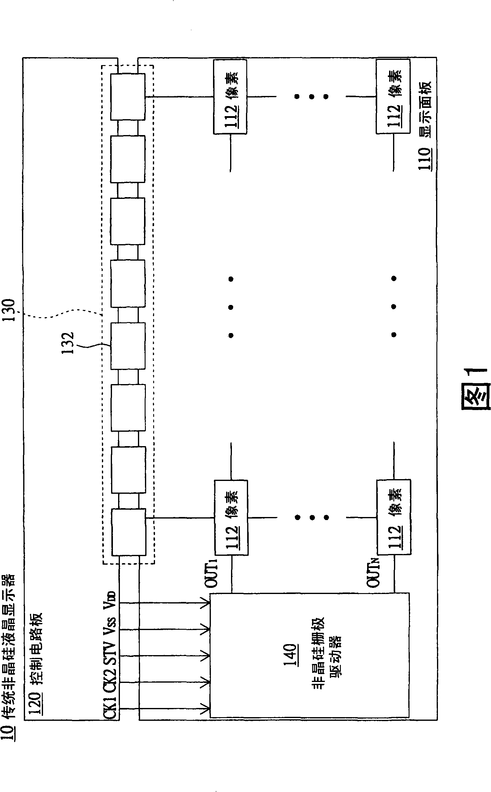
[0012] However, when the threshold voltage of the amorphous silicon thin film transistor shifts, it will not only affect the normal operation of the amorphous silicon gate driver, but also reduce the service life of the amorphous silicon gate driver

Method used


Image

  • Compensating circuit for improving threshold voltage off set and process thereof
  • Compensating circuit for improving threshold voltage off set and process thereof
  • Compensating circuit for improving threshold voltage off set and process thereof

Examples


no. 1 example

[0046] Please refer to FIG. 8 , which shows a block diagram of the compensation circuit 220 according to the first embodiment of the present invention. The compensation circuit 220 includes a current sensor 222 (Current Sensor) and a voltage regulator 224 . The current sensor 222 is used to sense the operating current I SS , and output the induced current I accordingly sen . Voltage regulator 224 according to the induced current I sen The size of the second operating voltage V corresponding to the adjustment DD voltage level.

[0047] The voltage adjusting device 224 includes a comparator 2242 and a voltage output unit 2244 . The comparator 2242 compares the sense current I sen with reference current value I ref If they are the same, the comparison signal S1 is output to the voltage output unit 2244 . If the induced current I sen greater than the reference current value I ref , the voltage output unit 2244 converts the second operating voltage V according to the comp...

no. 2 example

[0059] Please refer to FIG. 12 , which shows a block diagram of a compensation circuit 320 according to a second embodiment of the present invention. The compensation circuit 320 differs from the compensation circuit 220 in that:

[0060] The voltage adjusting device 324 of the compensation circuit 320 further includes a current-to-voltage converter 3246 . The current-to-voltage converter 3246 will sense the current I sen converted to the sensed voltage V sen Output to comparator 3242.

[0061] The comparator 3242 compares the induced voltage V sen with reference voltage value V ref If they are the same, the comparison signal S4 is output to the voltage output unit 2244 . where the reference voltage value V ref According to the reference current value I ref And get.

[0062] If the induced voltage V sen greater than the reference voltage value V ref , the voltage output unit 2244 converts the second operating voltage V according to the comparison signal S4 DD from t...


PUM


Abstract

Disclosed are a compensation circuit and the method thereof for improving the threshold voltage offset. The compensation circuit comprises a current sensor and a voltage regulation device. The current is used for sensing the current responded and generated after the amorphous silicon gate driver receives the first operating voltage and the second operating voltage. The current sensor outputs the sensing current according to the operating current. The voltage regulation device correspondingly regulates the second operating voltage according to the sensing current to improve the threshold voltage offset.

Description

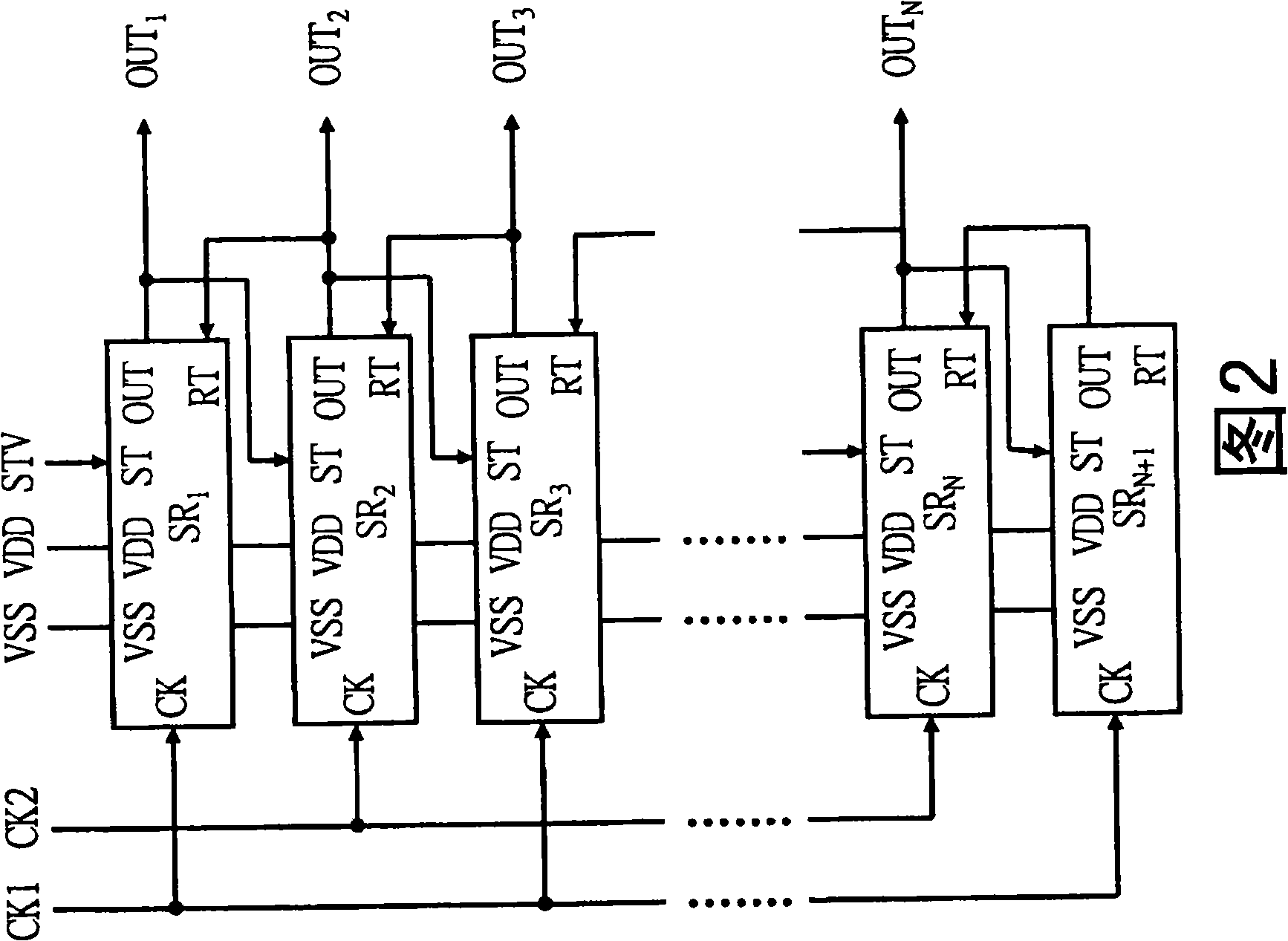
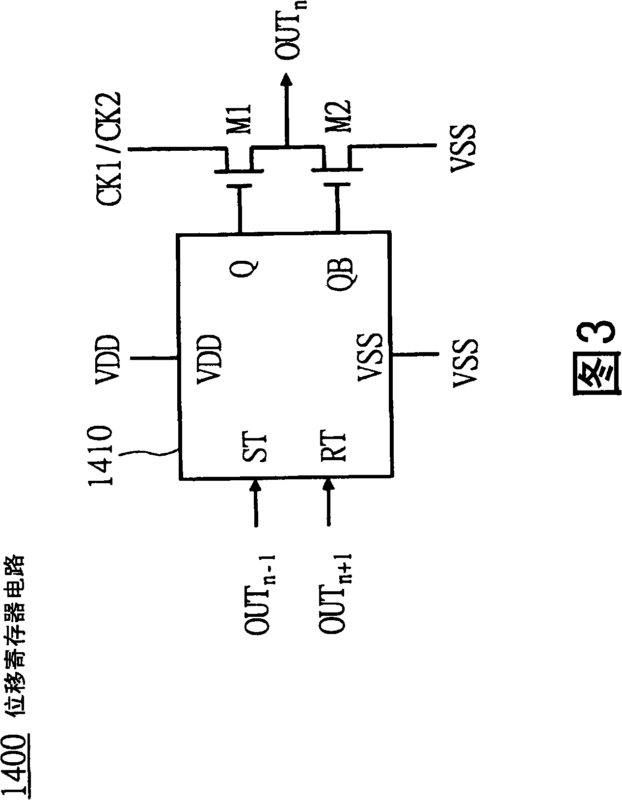
technical field [0001] The present invention relates to a compensation circuit and method for improving threshold voltage offset, and in particular to a compensation circuit and method for improving threshold voltage offset of an amorphous silicon gate driver. Background technique [0002] With the growth of amorphous silicon manufacturing technology, the industry has now been able to use the amorphous silicon gate manufacturing technology (Amorphous Silicon Gate, ASG) to integrate the gate driver on the display panel. This gate driver is also called amorphous silicon gate. pole drive. Since the amorphous silicon gate driver is formed by the amorphous silicon thin film transistor (Amorphous Silicon Thin Film Transistor, a-si TFT) in the display panel, it can reduce the use requirements of the original driver chip and the number of contacts of external components. The reliability of the product will be improved and the production cost will be reduced. [0003] Please refer ...

Claims


Application Information

Patent Timeline
IPC IPC(8): G09G3/20G09G3/36G02F1/133
Inventor 蔡进成
Owner INNOLUX CORP
Learn More