
Method for processing fractured connecting rod for car engine

An automotive engine and processing method technology, applied in metal processing equipment, metal processing mechanical parts, manufacturing tools, etc., can solve the problems of high price, non-conformity, large cumulative error, etc., achieve low manufacturing accuracy requirements, and improve processing efficiency. , the effect of improving performance

Active Publication Date: 2009-01-28
苏垦银河汽车部件盐城有限公司
View PDF0 Cites 31 Cited by
  • Summary
  • Abstract
  • Description
  • Claims
  • Application Information

AI Technical Summary

Problems solved by technology

But the disadvantages are: 1. There are many processes, multiple clamping and positioning during the processing process, resulting in a large cumulative error, which affects the accuracy and quality of the product; ) should be left with a margin of 4-6mm for sawing according to the process requirements; 3. The assembly of the connecting rod body and the connecting rod cover should be positioned and tightened by bolts, thereby affecting the accuracy of the bolt holes and the accuracy of the bolts. High manufacturing precision is required, and the bolts must be high-strength bolts that can withstand shear force and positioning accuracy requirements
4. The material used for the connecting rod is alloy structural steel, and the forging blank must be quenched and tempered, which increases the cost of heat treatment
The price of special-purpose equipment is very expensive, about 12 million yuan per set. If a special equipment for expansion-breaking connecting rods is used, it cannot cover various types of connecting-rod assemblies. Multiple sets of special-purpose equipment for expansion-breaking connecting rods are needed to meet the requirements. This kind of equipment investment is risky and does not conform to my country's national conditions.

Method used


Image

  • Method for processing fractured connecting rod for car engine
  • Method for processing fractured connecting rod for car engine
  • Method for processing fractured connecting rod for car engine

Examples


Embodiment Construction

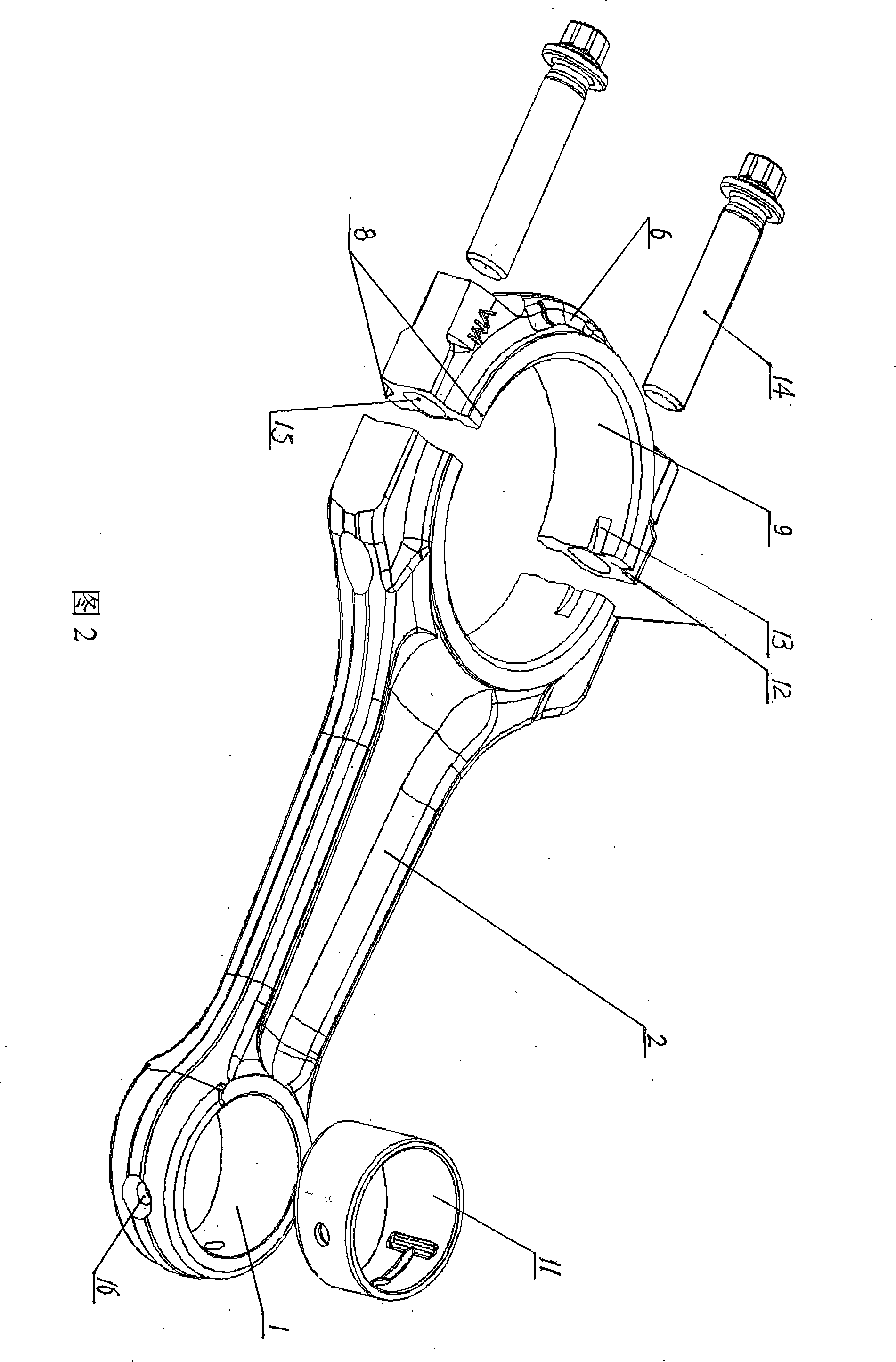
[0019] Referring to Fig. 2, the connecting rod processed by the present invention consists of: small head hole 1, bushing 11, connecting rod body 2, fracture surface (bonding surface) 12, slip groove 13, big head hole 9, bolt 14, connecting rod cover 6 , upper and lower planes 8, bolt holes 15, small head oil holes 16, etc., are generally made of high carbon steel materials.

[0020] refer to image 3 , the main technological process of the present invention is: A, process connecting rod upper and lower plane; B, car small head hole; C, boring big and small head hole; D, drill bolt hole and tap; Bursting; G, assembly; H, fine boring and large and small head holes; I, fine grinding and large and small head holes; J, inspection. ...to the follow-up process.

[0021] With reference to Fig. 2,3,4,5,6,7,8, the concrete operation description of the present invention:

[0022] A. Machining the upper and lower planes of the connecting rod: use a double-end grinder to process the upp...


PUM


Abstract

The invention discloses an expansion-breaking processing method of a connection rod used for an automobile engine which is also applied to the processing of the connection rods of a diesel engine, a barge engine, etc. The method is mainly characterized by adopting a technical flow as follows: processing the upper plane and the lower plane of the connection rod; machining a small end hole; boring a small end hole and a big end hole; drilling a bolt hole and tapping; drawing an expansion-breaking stress slot; expansion-breaking; assembling; preciously boring the small end hole and the big end hole; preciously milling the small end hole and the big end hole, detecting, etc. Practical applications proves that the method reduces accumulated errors, thus effectively improving the use performance of a connection rod assembly; reducing working procedure and processing precision as well as improving efficiency; the method adopts a common device and a special clamp to finish the expansion-breaking processing, thus being applied to the multi-variety small-batch production of the connection rod and simultaneously reducing the investment risk.

Description

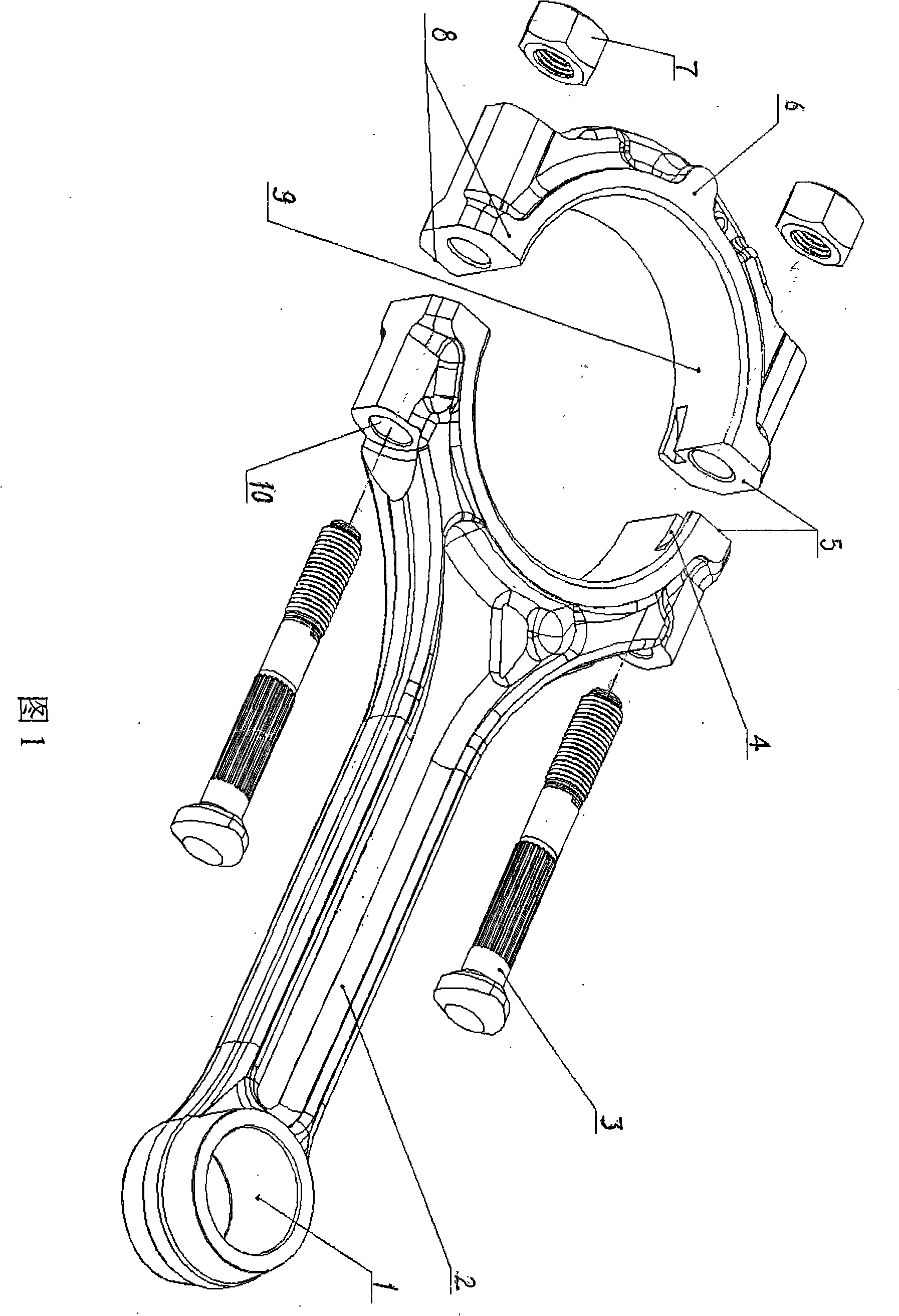
1. Technical field [0001] The invention relates to a mechanical processing technology, which is mainly applicable to the processing of connecting rods of automobile engines, and also applicable to the processing of connecting rods of diesel engines, yacht engines and the like. 2. Background technology [0002] Usually the processing method of connecting rod body and connecting rod cover (see Figure 1), the connecting rod is mainly composed of small head hole 1, connecting rod body 2, bolt 3, slip groove 4, joint surface 5, connecting rod cover 6, nut 7 , upper and lower planes 8, big head holes 9, and bolt holes 10 etc. are formed. Its main technological process is: processing the upper and lower planes 8 of the connecting rod; sawing off the connecting rod cover 6 and the connecting rod body 2; milling and grinding the joint surface 5 of the connecting rod body and the connecting rod cover; The rod body 2 and the connecting rod cover 6 are combined with the big head hole 9...

Claims


Application Information

Patent Timeline
Patent Type & Authority Applications(China)
IPC IPC(8): B23P15/00B23Q3/00B23D43/00
Inventor 李发文邓伟杨海祥陈亚萍张勇杨建辉冀会平施惠杜建华刘瑞红
Owner 苏垦银河汽车部件盐城有限公司
Learn More