
Method and system for compensating inductance deviation and implementing circuit elements thereof

A technology of circuit components and inductance current, which is applied in the field of compensating inductance deviation circuit components, compensating inductance deviation, and compensating inductance deviation systems, which can solve problems such as errors and inaccurate output currents of flyback converters

Inactive Publication Date: 2009-01-21
ACTIVE SEMI SHANGHAI +1
View PDF0 Cites 27 Cited by
  • Summary
  • Abstract
  • Description
  • Claims
  • Application Information

AI Technical Summary

Problems solved by technology

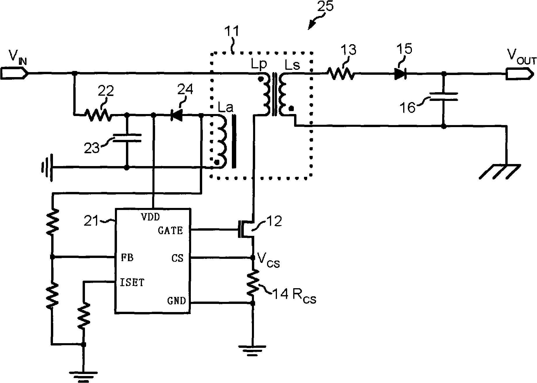
All of these variations will generate errors, resulting in an inaccurate output current of the flyback converter 25

Method used


Image

  • Method and system for compensating inductance deviation and implementing circuit elements thereof
  • Method and system for compensating inductance deviation and implementing circuit elements thereof
  • Method and system for compensating inductance deviation and implementing circuit elements thereof

Examples


Embodiment Construction

[0031] Unless otherwise stated, in this embodiment below, the inductive switch refers to the main power switch tube 44 , and the switch pin refers to the SW terminal or SW pin (that is, 99 in the drawings). For the convenience of expression and writing, the present invention adopts different technical terms for the same technical feature, but its substantive meaning or representative or pointed objects are the same, such as the so-called primary inductance (referring to the inductance on the primary winding or primary coil), The primary winding and the primary coil are all 39 in the accompanying drawings; for another example, the secondary inductance (referring to the inductance on the secondary winding or the secondary coil), the secondary winding and the secondary coil are also the same, all of which are 40 in the accompanying drawings; There are also auxiliary level inductance (refers to the inductance on the auxiliary winding, auxiliary level winding or auxiliary level coil...


PUM


Abstract

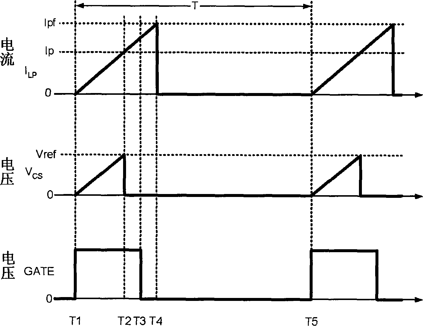
The present invention discloses a method, a system and an implementing circuit element for compensating inductance variation. A comparing circuit and a control loop are used to maintain the peak level of current flowing through an inductor of a flyback converter. An inductor switch control signal controls an inductor switch through which the inductor current flows. The inductor current increases at a ramp-up rate during a ramp time and stops increasing at the end of the ramp time. The comparing circuit generates a timing signal that indicates a target time at which the inductor current would reach a predetermined current limit if the inductor current continued to increase at the ramp-up rate. The control loop then receives the timing signal and compares the target time to the end of the ramp time. The pulse width of the inductor switch control signal is increased when the target time occurs after the end of the ramp time. Adjusting the pulse width controls the peak of the inductor current.

Description

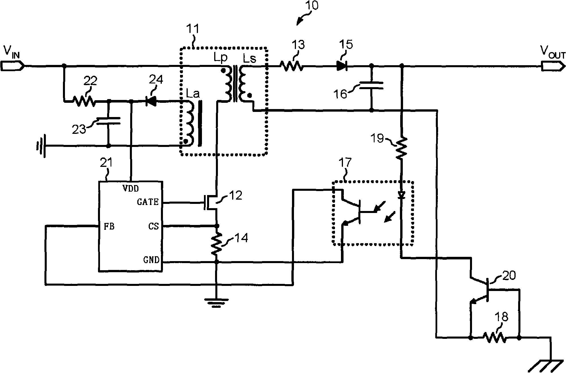
technical field [0001] The invention relates to the field of power conversion, in particular to a method for compensating inductance deviation. It also relates to a system for compensating inductance deviations. In addition, it also relates to a circuit element for realizing compensation of inductance deviation. Background technique [0002] Over the years, various control ICs (integrated circuits) for constant current and constant voltage flyback power supplies have been developed and applied, and their applications include off-line AC / DC (alternating current / direct current) power adapters, chargers, and mobile devices. backup power. [0003] figure 1 It is a circuit diagram of an existing typical constant current output flyback converter 10 controlled by the secondary side of the transformer 11 . The transformer 11 comprises three windings: a primary winding Lp, a secondary winding Ls and an auxiliary winding La. The flyback converter 10 includes an external MOSFET (M...

Claims


Application Information

Patent Timeline
Patent Type & Authority Applications(China)
IPC IPC(8): H02M3/28
CPCH02M2001/0009H02M3/33523H02M3/33507H02M1/0009
Inventor 黄树良迈特·格镶龚大伟
Owner ACTIVE SEMI SHANGHAI
Learn More