
Electrically-driven liquid crystal lens and stereoscopic display device using the same

A technology of liquid crystal lens and electric drive, which is applied in the direction of electrical components, three-dimensional systems, static indicators, etc., and can solve the problems of discontinuous lens shape of electric drive liquid crystal lens, complex orientation of liquid crystal controlled by electric field, drooping of electric drive liquid crystal lens, etc.

Active Publication Date: 2009-01-14
LG DISPLAY CO LTD
View PDF1 Cites 38 Cited by
  • Summary
  • Abstract
  • Description
  • Claims
  • Application Information

AI Technical Summary

Problems solved by technology

As a result, it is extremely difficult to form electrically actuated liquid crystal lenses with flattened parabolic lens surfaces suitable for obtaining the same optical effects as actual lenses
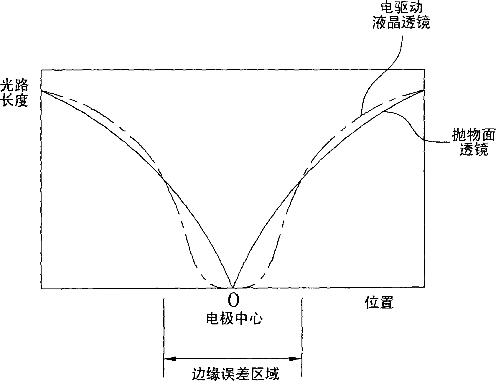
[0023] Second, in the case of a large-area display device, the central area of ​​the lens away from the edge area of ​​the lens where electrodes for applying high voltages are practically unaffected by the electric field, the use of the electric field to control the orientation of the liquid crystal becomes complicated, and according to the electric field Causes severe deformation of the lens shape
As required, when control in the central region of the lens is difficult or impossible, the resulting EALC lens has a discontinuous lens profile, which renders EALC lens ineffective as a lens
[0024] Third, an electrically driven liquid crystal lens configured by a vertical electric field between an electrode applied with a single high voltage and an electrode formed on the entire surface of the substrate opposite to the electrode applied with the high voltage can sag

Method used


Image

  • Electrically-driven liquid crystal lens and stereoscopic display device using the same
  • Electrically-driven liquid crystal lens and stereoscopic display device using the same
  • Electrically-driven liquid crystal lens and stereoscopic display device using the same

Examples


Embodiment Construction

[0049] Now, an electrically driven liquid crystal lens and a stereoscopic display device using the same according to a preferred embodiment of the present invention will be described in detail, examples of which are illustrated in the accompanying drawings. Wherever possible, the same reference numbers will be used throughout the drawings to refer to the same or like parts.

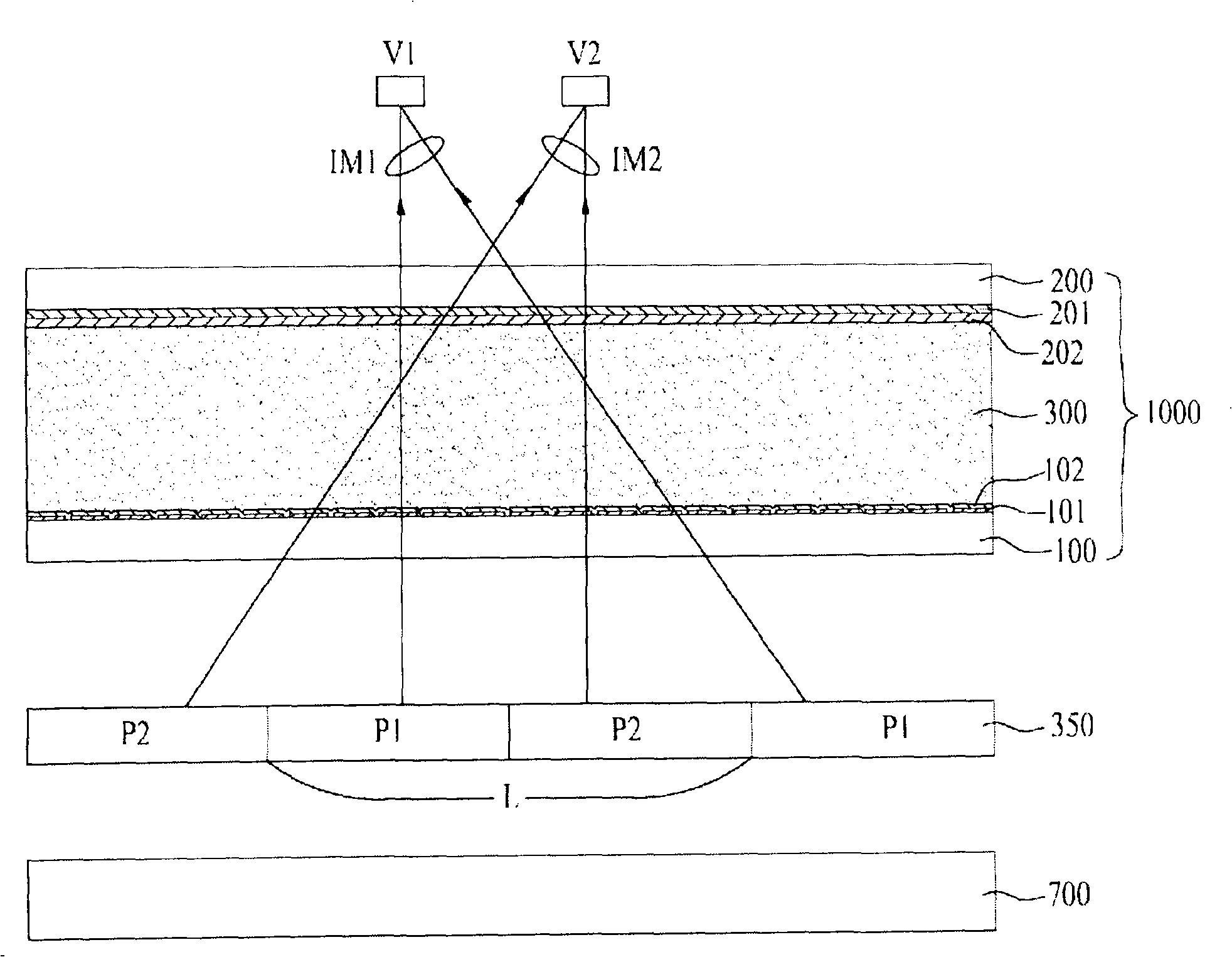
[0050] image 3 is a sectional view illustrating a stereoscopic display device using an electrically driven liquid crystal lens according to a first embodiment of the present invention, Figure 4 is a diagram image 3 Cross-sectional view of an electrically driven liquid crystal lens.

[0051] Such as image 3 As shown in , the stereoscopic display device having the electrically driven liquid crystal lens according to the first embodiment of the present invention includes an electrically driven liquid crystal lens 1000 driven by applying a voltage and used as a lens, disposed under the electrically dri...


PUM

PropertyMeasurementUnit
thicknessaaaaaaaaaa

Abstract

An electrically-driven liquid crystal lens, and a stereoscopic display device using the same, including first and second substrates arranged opposite each other and including an active region having a plurality of lens regions and a pad region defined at an outer rim of the active region, a plurality of first electrodes formed on the first substrate to correspond to the respective lens regions and spaced apart from one another, a second electrode formed on the entire surface of the second substrate, a voltage source to apply different voltages to the plurality of first electrodes, respectively, and to apply a ground voltage to the second electrode, and a liquid crystal layer interposed between the first substrate and the second substrate.

Description

[0001] This application claims the benefit of Korean Patent Application No. 2007-069414 filed on July 11, 2007 and Korean Patent Application No. 2007-106012 filed on October 22, 2007, which are incorporated by reference as if in This fully clarifies. technical field [0002] The present invention relates to a liquid crystal display device, in particular to an electrically driven liquid crystal lens and a stereoscopic display device using it, wherein the lens realized according to the liquid crystal orientation can obtain a smooth parabolic lens surface by changing the electrode structure, thereby reducing The cell gap of the small liquid crystal layer and a stable profile are obtained even when applied to a large-area display device. Background technique [0003] At present, services for the rapid dissemination of information based on high-speed information communication networks have developed from simple "listening" services, such as the current telephone, to " audio-visu...

Claims


Application Information

Patent Timeline
Patent Type & Authority Applications(China)
IPC IPC(8): G02F1/29G02F1/133G02F1/1343G02B27/22H04N13/00H04N15/00
CPCG02B5/1814G02F1/0123G02F1/1337G02F1/1343
Inventor 郑圣珉林希珍
Owner LG DISPLAY CO LTD
Learn More