
Encapsulated refrigeration compressor

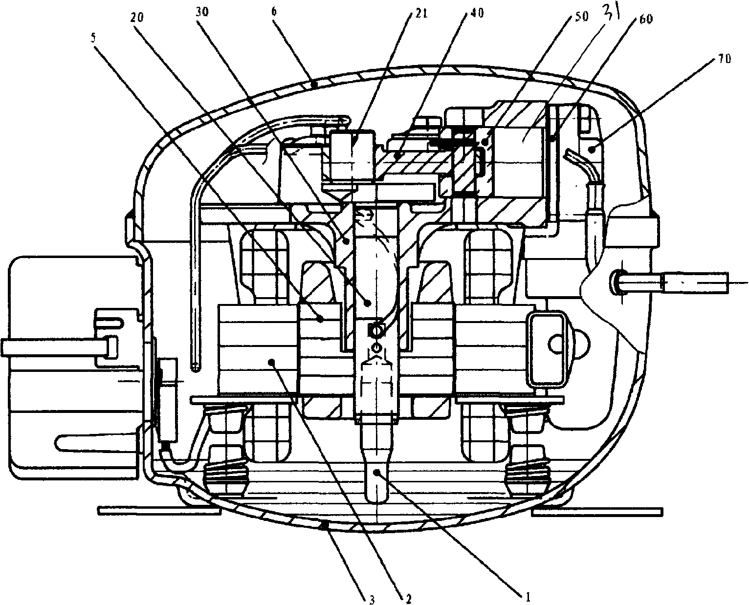
A refrigeration compressor and a sealed technology, applied in the field of compressors, can solve problems such as large loss, and achieve the effects of simple structure, easy improvement and convenient assembly.

Inactive Publication Date: 2009-01-14
GUANGZHOU REFRIGERATION CO LTD
View PDF1 Cites 5 Cited by
  • Summary
  • Abstract
  • Description
  • Claims
  • Application Information

AI Technical Summary

Problems solved by technology

[0008] In the prior art, in order to reduce the friction loss of the main bearing, the diameter of the main bearing and the length of the friction pair can be reduced as much as possible, but due to the requirements of strength and minimum oil supply, it cannot be reduced without limit
[0009] In order to reduce friction loss, the structure of thrust ball bearings has been adopted in the crankshaft support of the hermetic compressor (such as the crankshaft piston refrigerator compressor with patent No. 02260924.5), which can reduce axial friction loss, but the main function of the crankshaft The bearing is still frictional and sliding, and the loss is relatively large

Method used


Image

  • Encapsulated refrigeration compressor
  • Encapsulated refrigeration compressor
  • Encapsulated refrigeration compressor

Examples


Embodiment 1

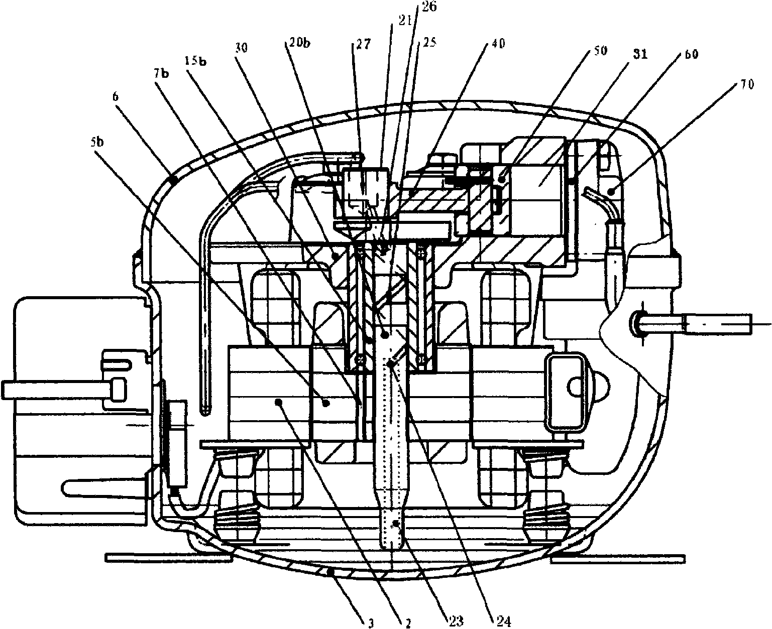
[0034] refer to figure 2 , Fig. 5, Fig. 6 and Fig. 7, a kind of hermetic refrigeration compressor provided by the present invention, it has sealed shell 3 and 6, has the electric motor that is made up of stator 2 and rotor 5b in the sealed shell and is driven by this motor The gas compression device comprises a cylinder block 30, a cylinder 31, a valve group 60, a cylinder head 70, a piston 50, a piston connecting rod 40, and a crankshaft 20b. Mounting hole, the crankshaft 20b passes through the crankshaft mounting hole, one end of the crankshaft 20b has an eccentric shaft 21, the piston connecting rod 40 connects the eccentric shaft 21 with the piston 50 placed in the cylinder 31, and the motor stator 2 is fixedly installed on the cylinder base 30 , the crankshaft 20b has a lubricating oil supply passage: oil suction hole 23 → perforation 24 → spiral oil groove 25 → oblique perforation 26 → eccentric shaft hole 27, it is characterized in that: a double row ball bearing assem...

Embodiment 2

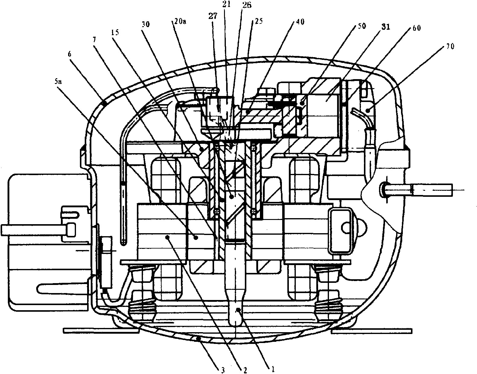
[0039] refer to image 3 , Fig. 8, Fig. 10 and Fig. 11, a kind of hermetic refrigerating compressor, it has sealed casing 3 and 6, has the electric motor that is made up of stator 2 and rotor 5a and the gas compressing device driven by this motor in the sealed casing , the gas compression device comprises a cylinder block 30, a cylinder 31, a valve group 60, a cylinder head 70, a piston 50, a piston connecting rod 40, a short crankshaft 20a and an oil suction pipe 1, the cylinder 31 is connected to the cylinder block 30, and the middle part of the cylinder block 30 is arranged Crankshaft installation hole, the short crankshaft 20a passes through the crankshaft installation hole, one end of the short crankshaft 20a has an eccentric shaft 21, the piston connecting rod 40 connects the eccentric shaft 21 and the piston 50 placed in the cylinder 31, and the motor stator 2 is fixedly installed on the cylinder On the seat 30, the short crankshaft 20a has a lubricating oil supply pass...

Embodiment 3

[0046] refer to Figure 9 , the short crankshaft 20a and the oil suction pipe 1 in the second embodiment are replaced by the crankshaft 20b of the first embodiment, and other structures and working methods are the same as those of the second embodiment.


PUM


Abstract

The invention provides a sealed type cold compressor which is provided with a sealed shell, an electric motor and a gas compression device are arranged in the sealed shell; the gas compression device comprises a cylinder block, a crank shaft, a cylinder, a piston and accessories, the middle part of the cylinder block is provided with a crank shaft mounting hole, one end of the crank shaft is provided with an eccentric shaft which is connected with the piston arranged in the cylinder by a piston connecting bar, and the crank shaft is provided with a lubricant supply passage; the compressor is characterized in that: the crank shaft mounting hole is internally sheathed with a double row ball bearing subassembly, the crank shaft passes through the axle hole of the double row ball bearing subassembly, and the rotor of the electric motor is sheathed in the inner ring over-long section of the crank shaft or the double row ball bearing subassembly. The double row ball bearing subassembly adopted by the invention can bear the axial load and radial load simultaneously to cause a main bearing on the crank shaft to move in a rolling friction way in the axial direction and the radial direction, thus greatly reducing the mechanical friction loss of the main bearing to improve the compressor performance; the sealed type cold compressor has the advantages of simple structure and convenient assembly, etc.

Description

technical field [0001] The invention relates to a refrigeration compressor, in particular to a compressor used in household and small refrigeration systems. Background technique [0002] The existing hermetic refrigeration compressor is installed in a closed shell, the motor and the cylinder are installed on a cylinder block, and the crankshaft with eccentric shaft that pushes the connecting rod-piston to reciprocate is assembled on the crankshaft hole of the cylinder block, and the crankshaft And the weight of the motor rotor installed on it is supported by the crankshaft hole upper end surface of the cylinder block. [0003] When the compressor is working, the motor drives the crankshaft to rotate, so that the force generated by the piston intermittently compressing the gas is transmitted to the eccentric shaft of the crankshaft and the main bearing of the crankshaft and the cylinder block through the connecting rod. [0004] Since the upper end surface of the crankshaft ...

Claims


Application Information

Patent Timeline
Patent Type & Authority Applications(China)
IPC IPC(8): F04B35/04F04B39/00
Inventor 陆海江王松陈忠华
Owner GUANGZHOU REFRIGERATION CO LTD
Learn More