Engine start-up device for hybrid vehicle power transmitting device
A technology for a power transmission device and a hybrid vehicle, which is applied in the field of a power transmission device and a starting engine of a hybrid vehicle, and can solve problems such as the speed change operation of an automatic transmission without special consideration of the increase of the engine speed, and the difficulty of rapidly increasing the engine speed, etc. Achieve rapid response, reduce control load, and improve responsiveness
- Summary
- Abstract
- Description
- Claims
- Application Information
AI Technical Summary
Problems solved by technology
Method used
Image
Examples
no. 1 example
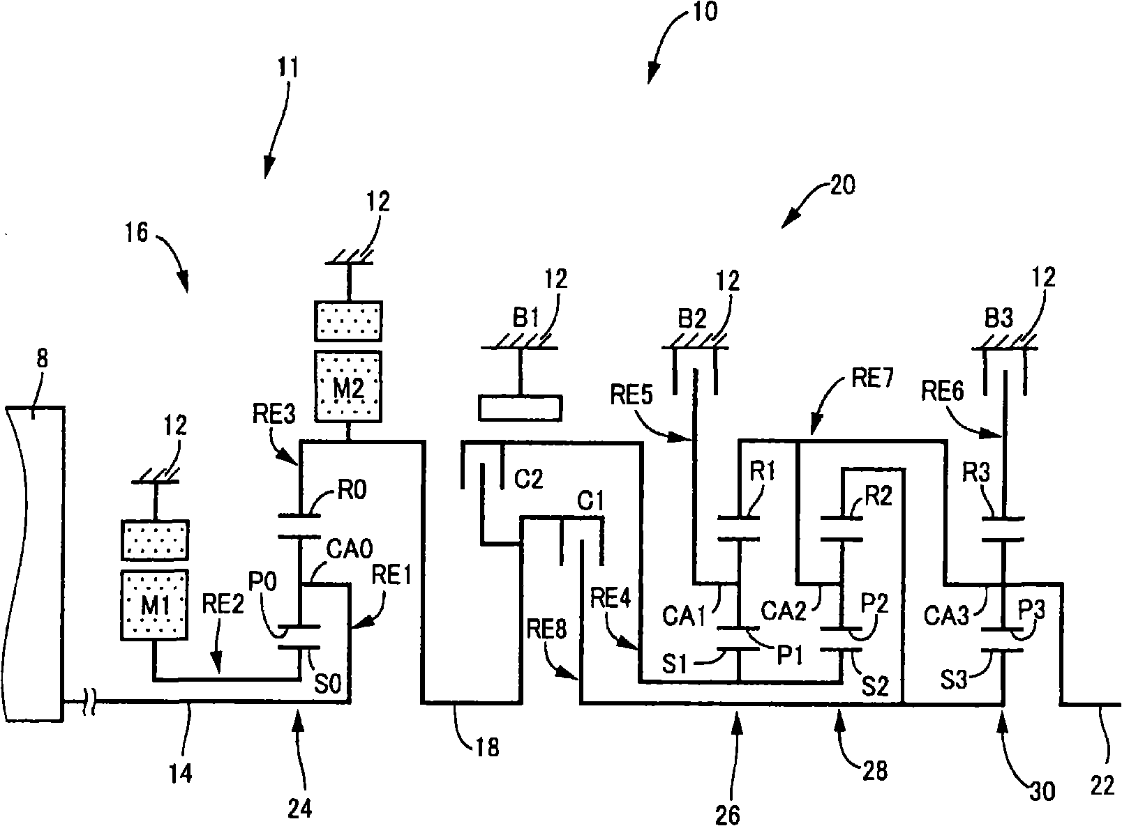
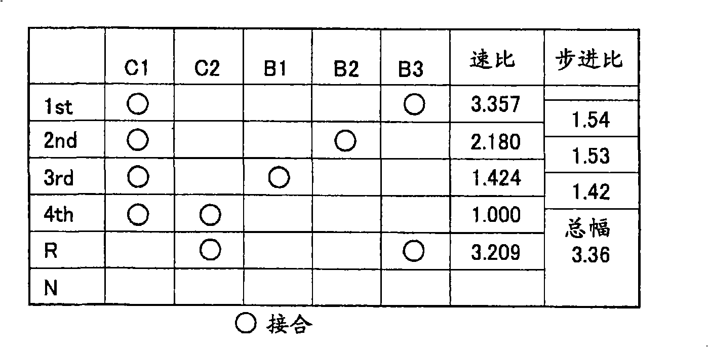
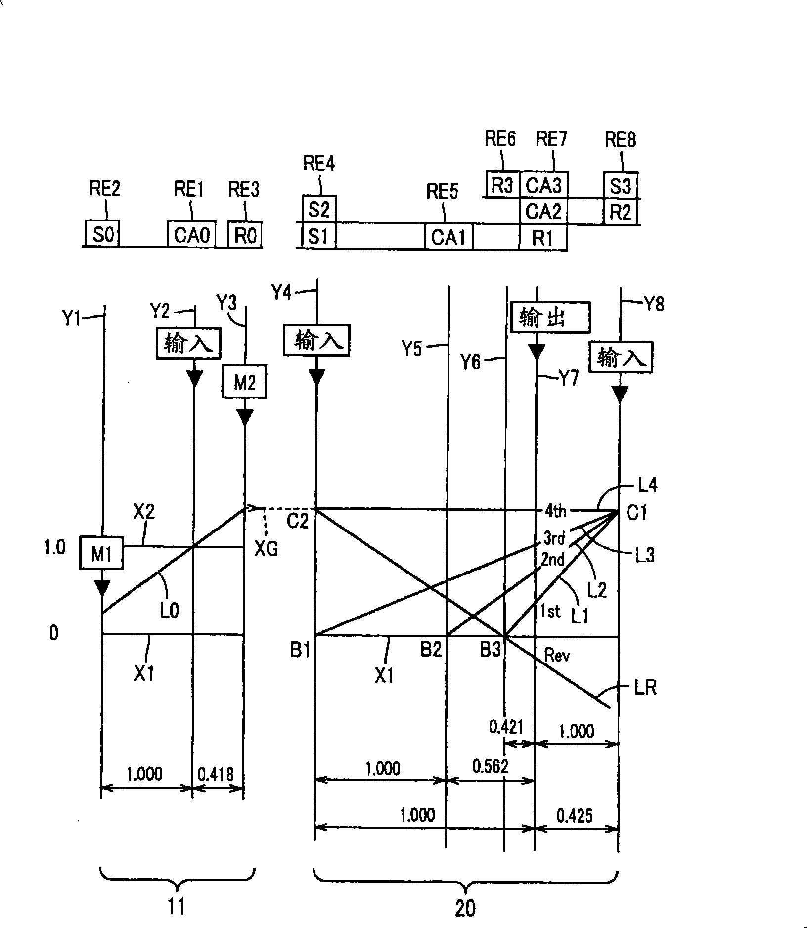
[0089] figure 1 It is a schematic diagram showing a speed change mechanism 10 that is a part of a power transmission device for a hybrid vehicle according to the present invention. Such as figure 1 As shown in , the transmission mechanism 10 includes a transmission housing 12 (hereinafter referred to as "housing 12") installed on the vehicle body as a non-rotating element, an input shaft 14 provided inside the housing 12 as an input rotating element, directly or The differential section 11, which is indirectly coaxially connected to the input shaft 14 through an unshown pulse absorbing damper (shock absorber) and serves as a continuously variable transmission section, is connected in series to the differential via a power transmission member (power transmission shaft) 18. speed part 11 and drive wheel 34 (see Figure 6 ) in the power transmission path between the automatic transmission portion 20, and the output shaft 22 connected with the automatic transmission portion 20 a...
no. 2 example
[0197] In the following second embodiment and the first embodiment Figure 1 to Figure 5 , Figure 7 and Figure 6 (corresponding to the second embodiment Figure 12 ) are the same as those shown. Therefore, descriptions and illustrations of these drawings will be omitted here for simplicity of description, but those descriptions and illustrations will be referred to when necessary. The control device of the second embodiment is represented in the form of "control device 110" Figure 4 middle. Hereinafter, the second embodiment will be described focusing on the points of difference in structure and operation compared with the first embodiment.
[0198] For the second embodiment, rotational speed sensors such as resolvers are used in the first and second motors M1 and M2 respectively, and each rotational speed sensor is capable of detecting rotational speed and rotational direction.
[0199] Considering the responsiveness and comfort demanded by the driver, when the vehic...
no. 3 example
[0247] The third embodiment adopts a configuration in which the electronic control unit 110 of the second embodiment is replaced with an electronic control unit 130 . The configuration of the third embodiment includes a Figure 12 The engine start control device 162 of the engine start control device 146 in the shown functional block diagram and the Figure 12 Other components that are the same as those of the second embodiment shown are engine start determining means 140 , shift state determining means 142 , motor limit state determining means 144 and shift control changing means 148 . Hereinafter, the third embodiment will be described focusing on different points.
[0248] The engine start determination means 140 determines that an engine start determination is made, and the shift state determination means 142 makes a determination to confirm that a shift is performed within the automatic shifting portion 20 . In addition, the motor restriction state determination means 1...
PUM
 Abstract
Description
Claims
Application Information
 - R&D
- Intellectual Property
- Life Sciences
- Materials
- Tech Scout
- Unparalleled Data Quality
- Higher Quality Content
- 60% Fewer Hallucinations
Browse by: Latest US Patents, China's latest patents, Technical Efficacy Thesaurus, Application Domain, Technology Topic, Popular Technical Reports.
© 2025 PatSnap. All rights reserved.Legal|Privacy policy|Modern Slavery Act Transparency Statement|Sitemap|About US| Contact US: help@patsnap.com


