
Keyboard apparatus

A keyboard device and keystroke technology, applied to stringed instruments, wind instruments, instruments, etc., can solve the problems of reducing space utilization and installation freedom, reducing space utilization and installation freedom, and reducing the freedom of installation parts, etc. , to achieve the effect of improving space utilization and installation freedom

Inactive Publication Date: 2009-01-07
YAMAHA CORP
View PDF2 Cites 6 Cited by
  • Summary
  • Abstract
  • Description
  • Claims
  • Application Information

AI Technical Summary

Problems solved by technology

[0008] However, if Figure 17 The conventional structure shown is provided with the first engaging portion 13B protruding below the key mounting portion 22A, and this structure has a problem in that space efficiency is reduced, and if, for example, a hammer, Substrates, cushions, and speakers reduce the degree of freedom for mounting components
[0009] Additionally, if Figure 17 The shown conventional structure is provided with the convex portion 21 extending below the key mounting portion 22A of the key frame 20, which has a problem in that the space utilization rate and the degree of freedom of installation are reduced due to the presence of the convex portion 21.
Another problem is that since the screw N needs to be longer than ordinary screws to be inserted into the first screw hole 16 and the second screw hole 21A provided in the key supporting part 13 and the key frame 20, it affects the screw holes that can be obtained by using the standard screw N. Increased productivity achieved
[0010] like Figure 17 The shown conventional structure is provided with the first reinforcing rib 23 extending below the key mounting portion 22A, which has a problem in that the space utilization rate and the degree of freedom of installation are reduced due to the existence of the first reinforcing rib 23.

Method used


Image

  • Keyboard apparatus
  • Keyboard apparatus
  • Keyboard apparatus

Examples


no. 1 example

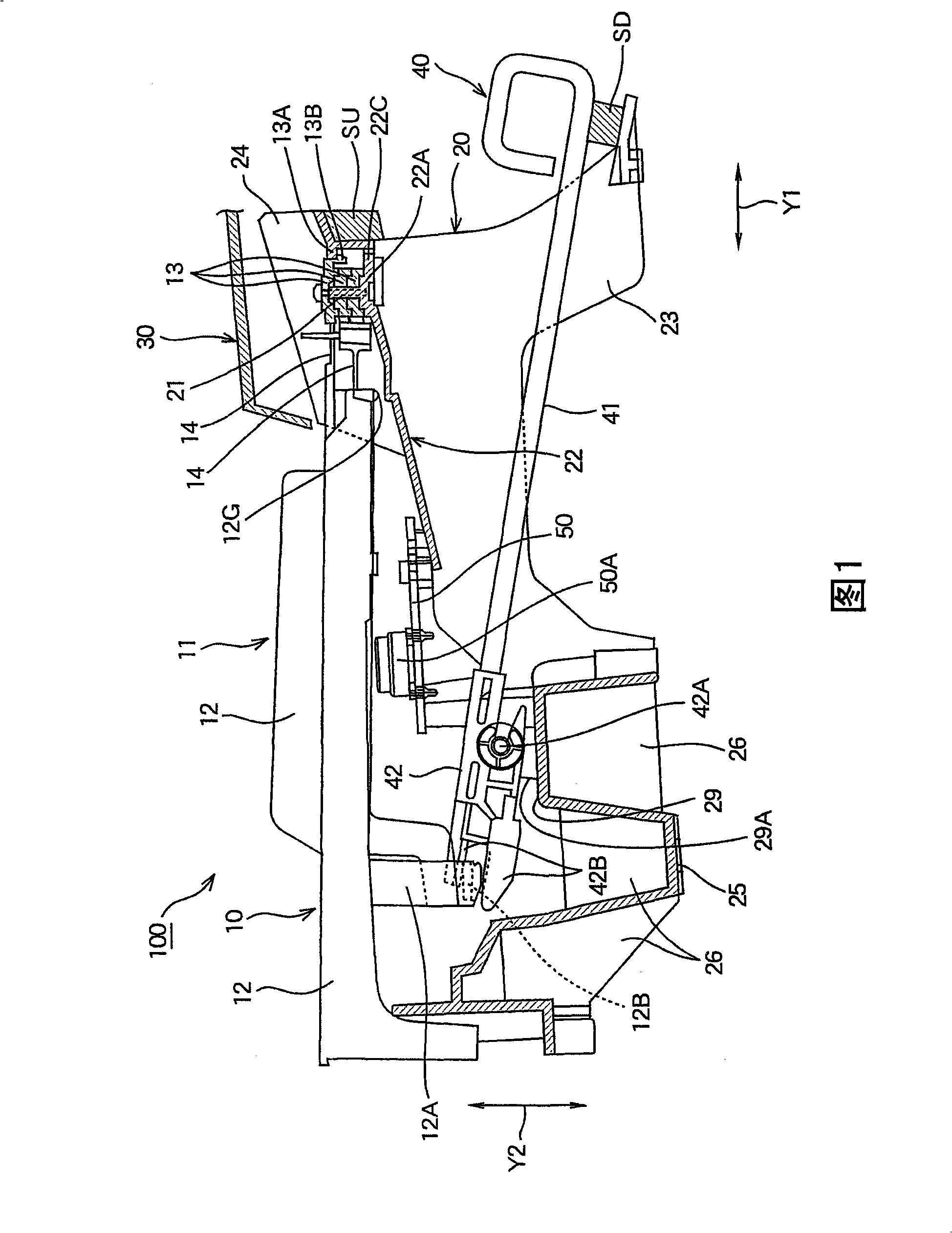
[0040] A first embodiment of the present invention will be described below with reference to the drawings. FIG. 1 is a sectional view showing a first embodiment of a keyboard device 100 of the present invention. figure 2 is a top view of the keyboard device 100 shown in FIG. 1 with the panel removed. image 3 It is a partially enlarged view of the vicinity of the key supporting portion 13 and the key mounting portion 22A of the keyboard device 100 shown in FIG. 1 .

[0041] A keyboard device 100 , exemplified as an electronic keyboard musical instrument, includes white key units 10 and black key units 11 serving as key units, a key frame 20 made of hard synthetic resin, and hammer members 40 , and above the keyboard device 100 And the rear panel 30 is set.

[0042] The white key unit 10 and the black key unit 11 are respectively provided with: one or more key bodies 12 for keystroke operations; rear); and a connecting portion 14 that pivotably connects the key body 12 to t...

no. 2 example

[0075] Next, a second embodiment of the present invention will be described with reference to the drawings. FIG. 8 is a cross-sectional view showing a second embodiment of the keyboard device 100 of the present invention. FIG. 9(A) is a partial plan view showing the black key unit 11 constituting the keyboard device 100 shown in FIG. 8 . FIG. 9(B) is a partial plan view showing the black key unit 11 and the key frame 20 constituting the keyboard device 100 shown in FIG. 8 . In Figures 8 and 9, with reference to Figures 1 to image 3 Components that are the same as those in the first embodiment described above are denoted by the same reference numerals, respectively, and detailed descriptions of these components are omitted here.

[0076] The keyboard device 100 includes a white key unit 10 and a black key unit 11 and a key frame 20 . The second embodiment is clearly different from the first embodiment in that it does not include the hammer member 40 . Similar to the first ...

no. 3 example

[0098] A third embodiment of the present invention will be described below with reference to the drawings. FIG. 13 is a sectional view showing a third embodiment of the keyboard device 100 of the present invention. Figure 14 It is a top view of the keyboard device 100 as shown in FIG. 13 , wherein the panel 30 is removed. Figure 15 It is a partially enlarged view of the vicinity of the key supporting portion 13 and the key mounting portion 22A of the keyboard device 100 shown in FIG. 13 .

[0099] A keyboard device 100 exemplified as an electronic keyboard instrument includes white key units 10 and black key units 11 serving as key units, a key frame 20 made of hard synthetic resin, and hammer members 40, and above the key frame and the keyboard device The rear of 100 is provided with panel 30 .

[0100] The white key unit 10 and the black key unit 11 are respectively provided with: one or more key bodies 12, which are used to withstand keystroke operations; side; and a c...


PUM


Abstract

In a keyboard device, key unit comprises: one or multiple key body; key support, for supporting body of every key; and connection part, for pivotally connecting the key support with key body along key stroke direction of key body. Key rack comprises: upper surface; and key mounting part, mounted on the upper surface, for mounting the key support of key unit. The key support of the key unit comprises a first coupling part, possessing hook structure or forced fit structure; the key mounting part of the key rack comprises a second coupling part. The key unit is mounted on the key rack, the second coupling part couples with the first coupling part. The second coupling part comprises through-hole or recess part for coupling with hook structure or forced fit structure of the first coupling part. The coupling position of the first coupling part and the second coupling part lies in upper part of key mounting part of the key rack.

Description

technical field [0001] The present invention relates to a keyboard device, and in particular to such a keyboard device comprising: a key unit provided with a plurality of key bodies, a key supporting portion for supporting each key body, and a key unit pivotally connected A connecting portion of the key supporting portion, these components are integrally provided by synthetic resin; and a key frame, on which a key mounting portion for locking the key supporting portion of the key unit is provided. Background technique [0002] For example in Japanese Patent No.3082696 discloses a kind of as Figure 17 keyboard device shown. Such as Figure 17 As shown in , the keyboard device includes white key units 10 and black key units 11 serving as key units, and a key frame 20 . White key unit 10 and black key unit 11 are respectively provided with: one or more key bodies 12, are used for keystroke operation; and a connecting portion 14 that pivotably connects the key body 12 to the ...

Claims


Application Information

Patent Timeline
Patent Type & Authority Applications(China)
IPC IPC(8): G10B3/12G10C3/12G10H1/34
CPCG10H1/346
Inventor 西田贤一
Owner YAMAHA CORP
Learn More