
Anode bonding device

A technology of anodic bonding and pressurizing devices, which is applied in the direction of microstructure devices, processing microstructure devices, instruments, etc., and can solve problems such as complex structures, insignificant effects, and insufficient equipment functions

Inactive Publication Date: 2011-05-11
HUAZHONG UNIV OF SCI & TECH
View PDF4 Cites 0 Cited by
  • Summary
  • Abstract
  • Description
  • Claims
  • Application Information

AI Technical Summary

Problems solved by technology

In the prior art, there are some leveling devices that help the samples to fit evenly, but the structure is relatively complicated and the effect is not significant
[0004] In addition, the existing anodic bonding technology is slightly insufficient in terms of equipment functions. In many practical cases, bonding under specific environmental conditions is required, such as vacuum environment, special atmosphere environment, and high pressure environment, etc., and in some cases The samples need to be specially treated and operated before the bonding operation. These requirements require a targeted design of the bonding equipment, and factors such as ease of operation, reliability and efficiency must be taken into account.

Method used


Image

  • Anode bonding device
  • Anode bonding device

Examples


Embodiment Construction

[0012] The present invention will be described in detail below with reference to the drawings and specific embodiments.

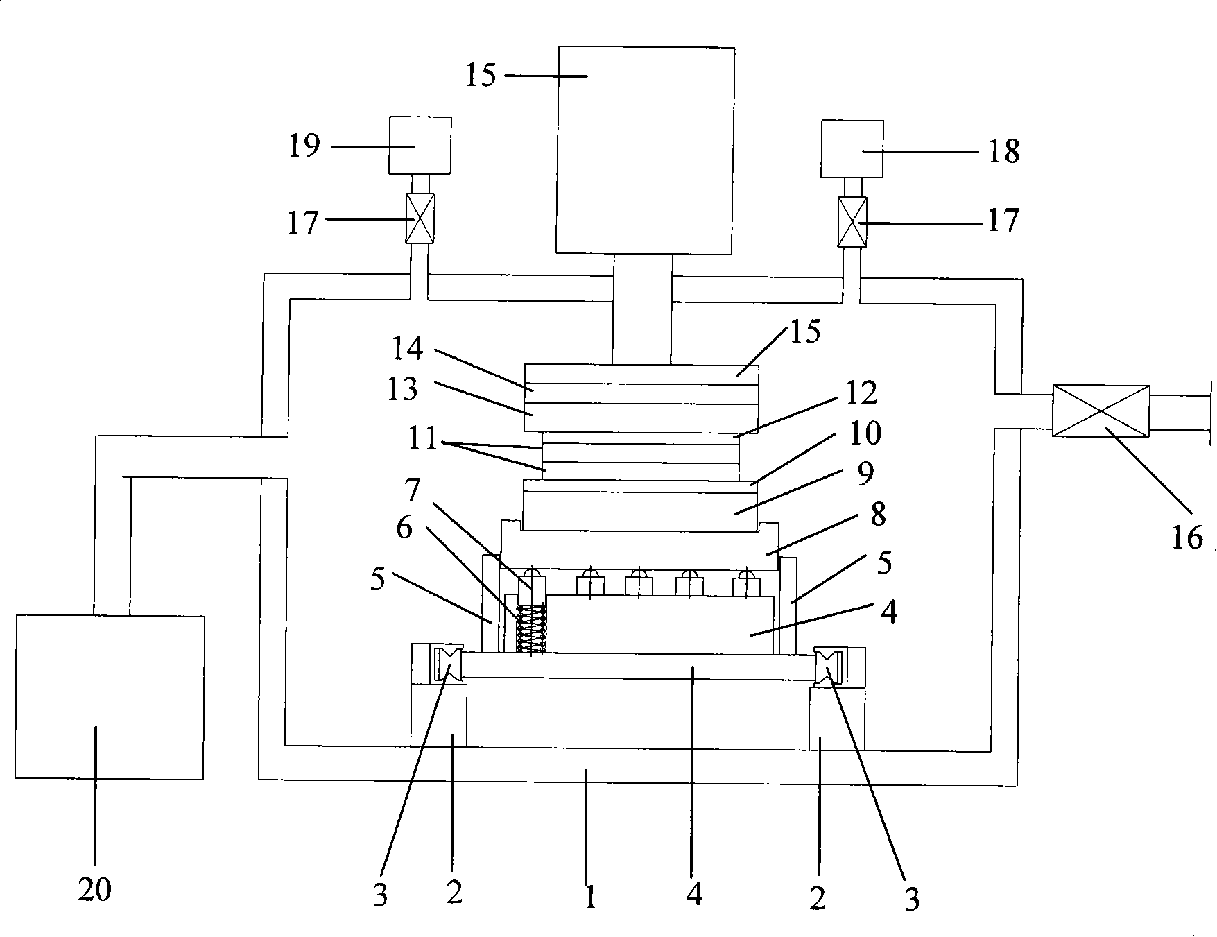
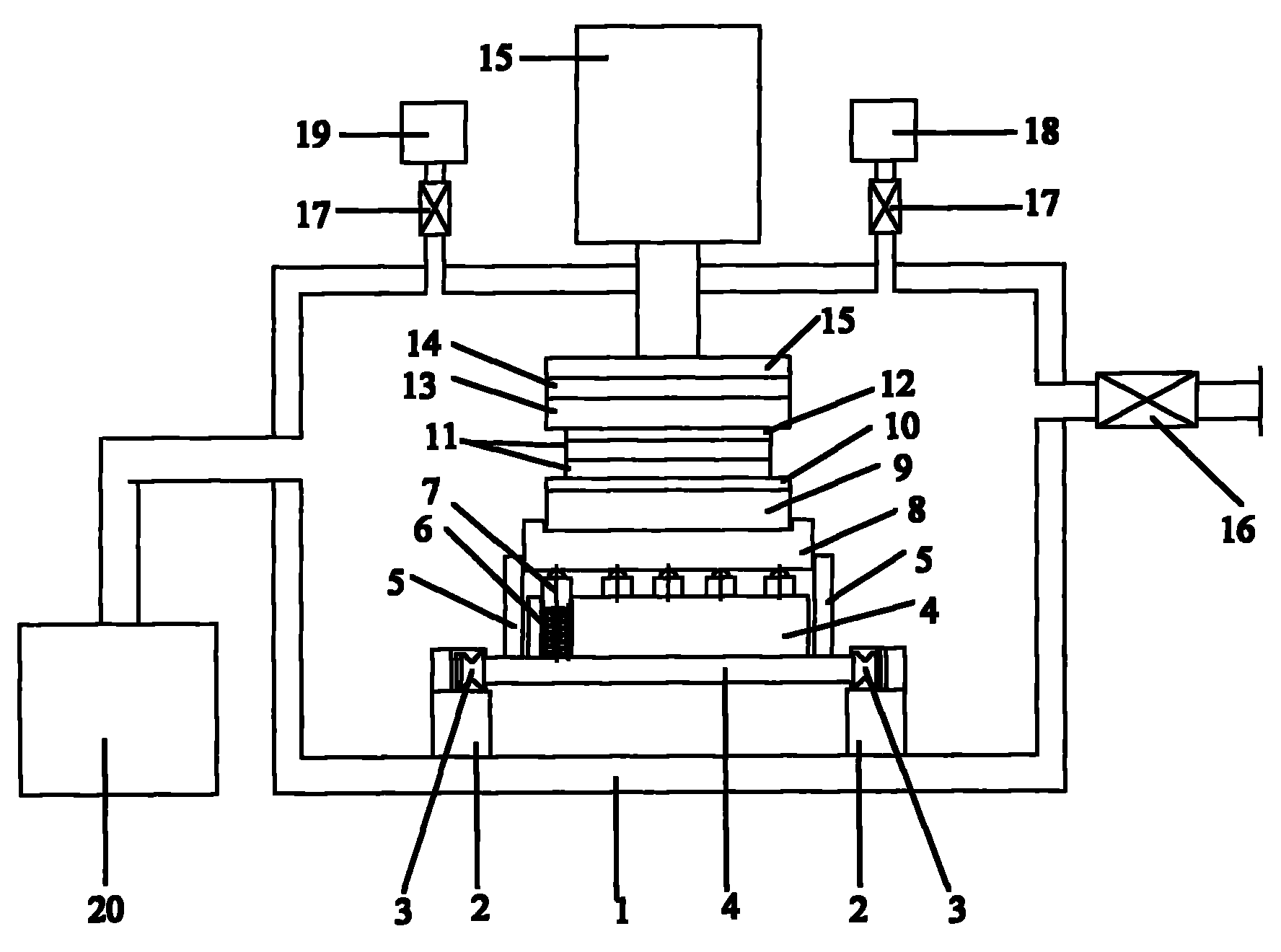
[0013] The anode bonding device of the present invention is such as figure 1 As shown, the vacuum chamber 1, the vacuum acquisition system 20, and the gas path interface 16 can achieve the vacuum and high-pressure specific atmosphere environment in the vacuum chamber 1, specifically: the vacuum system 20 evacuates the vacuum chamber, and a vacuum detection instrument 18 performs detection For the vacuum degree in the vacuum chamber, the vacuum obtaining system 20 can use a mechanical pump or a vacuum pump; for the high-pressure environment of a specific gas, vacuum is first performed, and then the specific gas is charged through the gas interface 16 and displayed by a high-pressure measuring instrument 19; The high-pressure measuring instrument is connected to the vacuum chamber 1 through a high airtight valve 17, and the high-pressure measuring instrument is ...


PUM


Abstract

The invention provides an anodic bonding device which essentially comprises an outer cavity, a pressure device, electrodes and a self-leveling device that is positioned at the bottom of the outer cavity; the self-leveling device is provided with a substrate which is equipped with a base plate and a lug boss positioned on the base plate; the interior of the lug boss is evenly provided with at least three counter bores which are internally provided with springs; the upper end of the spring is provided with a ball-end columella, the other end of the ball-end columella, which is in a hemispheric shape, extends out of the counter bore and is connected with the thermal insulation substrate, the periphery of the lug boss on the base plate is provided with three gag lever posts which are evenly distributed, the gag lever post is slightly higher than the contact face of the ball-end columella and the thermal insulation substrate, so as to limit thermal insulation substrate. In the invention, the self-leveling device can ensure that the whole bonding device forms an up and down floating structure, thus realizing the self-leveling during sample plate bonding and uniform attachment of sample plates.

Description

Technical field [0001] The present invention relates to the field of microelectromechanical systems, in particular to an anode bonding device. Background technique [0002] Anode bonding is a widely used bonding process in the field of microelectromechanical systems, mainly to achieve permanent bonding between metal and insulator. Its main feature is that the two samples that are closely bonded at a certain temperature form a permanent bond under the action of an electrostatic field, and finally a new conforming material is obtained. [0003] In the process of operation, the quality of the bonding between the samples directly affects the result and quality of the bonding. If the bonding between the samples is not uniform, the final bonding may fail. Therefore, it is effective to design a device that can automatically adjust To ensure the smooth completion of the bonding. The prior art provides some leveling devices that help the samples to be evenly attached, but the structure is...

Claims


Application Information

Patent Timeline
Patent Type & Authority Patents(China)
IPC IPC(8): B81C3/00
Inventor 甘志银张廷凯
Owner HUAZHONG UNIV OF SCI & TECH
Learn More