
A cleaning head for a porous plate

A cleaning head and porous plate technology, applied in the direction of cleaning methods using liquids, cleaning methods and utensils, chemical instruments and methods, etc., can solve the problem of water injection pressure, poor uniformity of water injection volume, no consideration of fluid pressure performance, and is not suitable for small Scale experiments and other issues to achieve the effect of improving efficiency, easy cleaning and maintenance, and simplifying the structure

Active Publication Date: 2011-11-30
上海裕隆生物科技有限公司
View PDF0 Cites 0 Cited by
  • Summary
  • Abstract
  • Description
  • Claims
  • Application Information

AI Technical Summary

Problems solved by technology

[0004] 1. The suction head and the water injection head are set separately, which inevitably requires the plate washer to install the two sets of cleaning heads on a set of manipulators and control them separately. Not only the structure is complicated, but the manufacturing cost of the plate washer is also relatively high.
[0005] 2. The number of water suction pipes and water injection pipes is equal to the number of holes in the perforated plate, so the whole plate can only be cleaned, and only the perforated plate with a fixed number of holes can be cleaned. The cleaning method is not flexible, and it is not suitable for some small scale experiment
[0006] 3. The length of the water suction pipe and the water injection pipe are the same, so that the water injection pipe can inject lotion into the corresponding hole only after the water suction pipe sucks out the dirty liquid from the microplate plate and the robot arm raises the cleaning head to a certain height. This leads to a waste of time, and the efficiency of washing the plate is low
[0007] 4. The water suction pipe and the water injection pipe are directly connected to the water outlet interface and the water injection interface through a pipeline respectively. Since the uneven pressure performance of the fluid in the pipeline is not considered, the water absorption pressure and water absorption capacity of each water suction pipe and water injection pipe , poor uniformity of water injection pressure, water injection volume, etc.
[0008] 5. The water suction pipe, water injection pipe and cleaning head cavity are easily blocked by liquid crystals and other dirt, and it is not easy to clean and maintain, resulting in greater inhomogeneity during use

Method used


Image

  • A cleaning head for a porous plate
  • A cleaning head for a porous plate
  • A cleaning head for a porous plate

Examples


Embodiment Construction

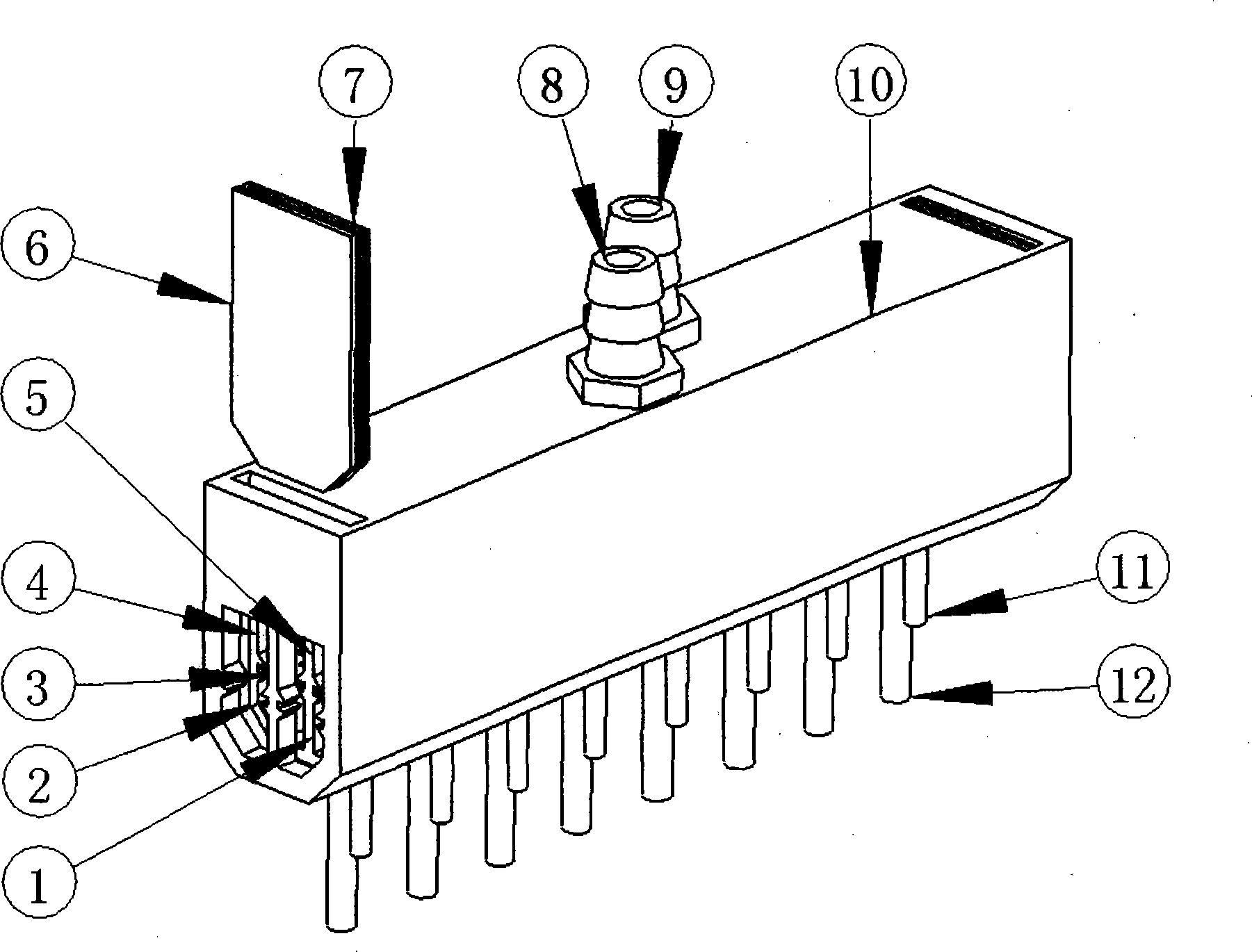
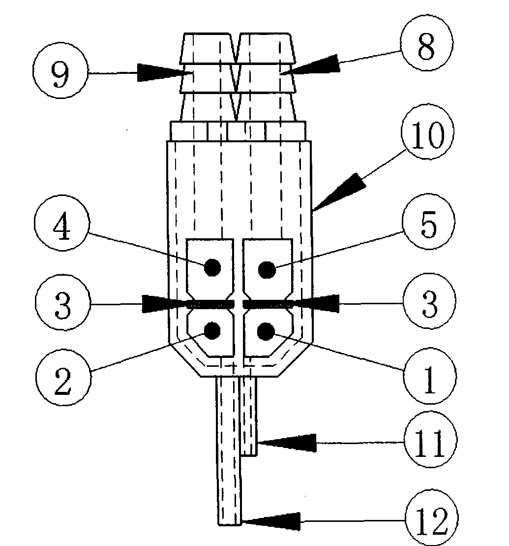
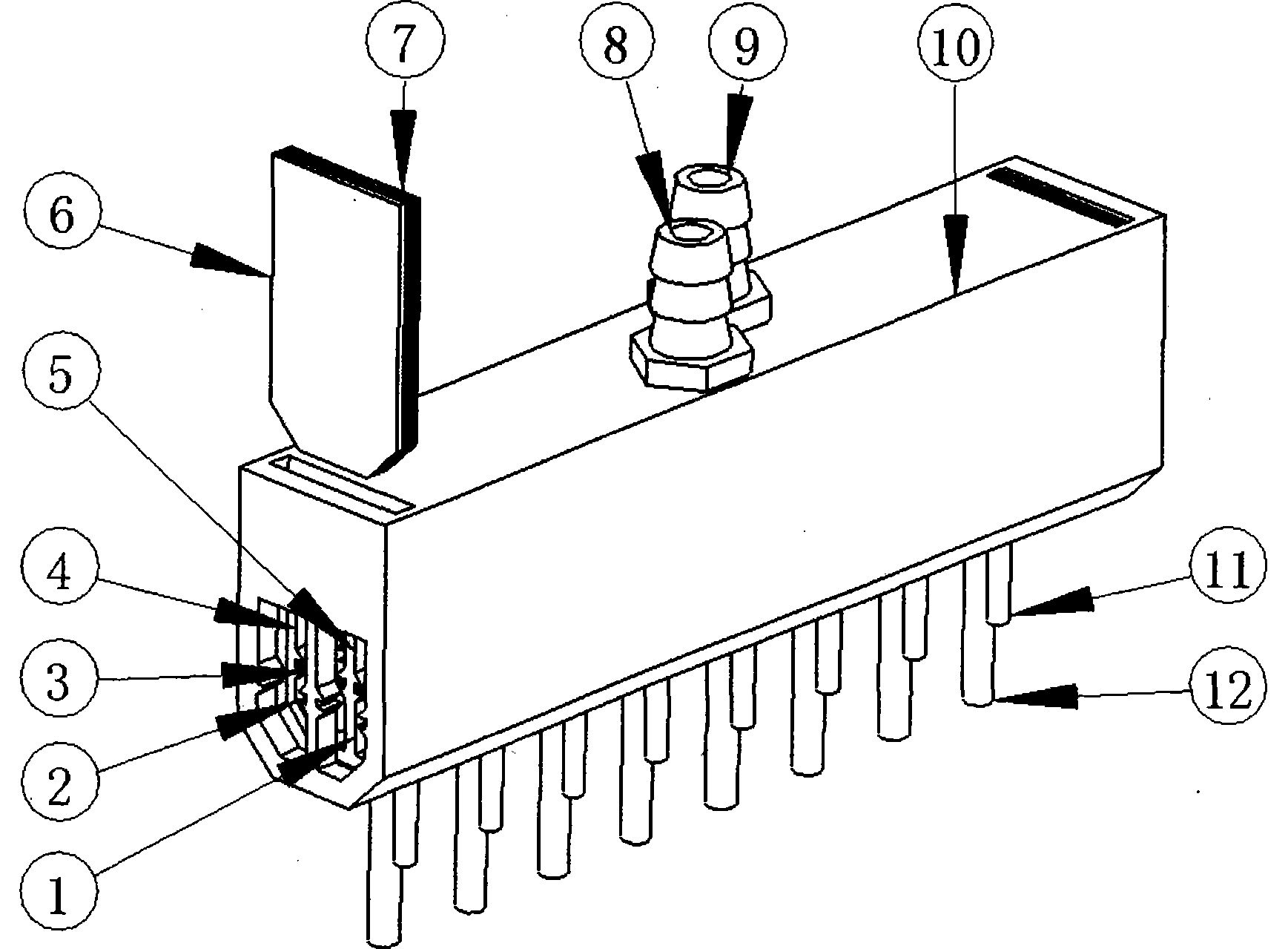
[0022] Below in conjunction with accompanying drawing, and the specific embodiment when the quantity of water suction pipe (12) and water injection pipe (11) is 8, the present invention is further described:

[0023] As shown in Figures 1 and 2, a cleaning head according to the present invention includes a row of water suction pipes (12), a row of water injection pipes (11), a water injection interface (8), a water outlet interface (9), The main body (10), two side plates (6), two side plate rubber pads (7), two porous partitions (3), and the main body (10), side plate rubber pads (7) and porous The partition plate (3) contains and separates four chambers formed by the water injection chamber (1), the water outlet chamber (2), the water injection buffer chamber (5), and the water outlet buffer chamber (4).

[0024] The water suction pipe (12) and the water injection pipe (11) are arranged in two rows at a certain distance, and the distance between the water suction pipe (12) a...


PUM


Abstract

The invention discloses a cleaning head for a porous plate and relates to cleaning equipment for a porous plate and a porous biological chip. It includes a row of water suction pipes, a row of water injection pipes, water injection interface, water outlet interface, main part, side plate, side plate rubber pad, porous partition, and the main part, side plate rubber pad and porous partition. The formed water injection chamber, water outlet chamber, water injection buffer chamber and water outlet buffer chamber. The water injection interface is connected to the water injection pipe through the water injection buffer chamber, the holes in the porous partition and the water injection chamber, and the water outlet interface is connected to the water suction pipe through the water outlet buffer chamber, the holes in the porous partition and the water outlet chamber. The side plate and the side plate rubber pad are fixed on the main part in a detachable manner by screws or slots on both sides of the main part, so as to facilitate cleaning and maintenance of the chambers, partitions and pipelines. The invention has the advantages of good uniformity, convenient cleaning, maintenance and use, flexible cleaning methods, suitable for experiments of various scales, and good operability.

Description

technical field [0001] The invention relates to cleaning equipment for porous plates and porous biochips used in medicine, biology, and chemical analysis, specifically, it is a key component in automatic enzyme standard washing equipment or biochip washing equipment. Background technique [0002] Enzyme-linked immunosorbent assay (ELISA) is an important technology in immunoassay. With the development of biotechnology, biochip detection technology is also more and more applied to immunoassay. In the ELISA experiment or biochip detection process, accurate and thorough washing is the key technology to ensure the accuracy and reliability of the results, because both ELISA experiments and biochip detection processes rely on washing to remove the solid-phase antibody ( or antigen) other substances other than the antigen (or antibody) that specifically binds, including: separated enzyme markers that are free in the liquid, substances that remain in the wells of the plate or on the ...

Claims


Application Information

Patent Timeline
Patent Type & Authority Patents(China)
IPC IPC(8): B08B3/00
Inventor 穆海东汪宁梅葛春刘聪蔡锦达
Owner 上海裕隆生物科技有限公司
Learn More