Double girder overhead viaduct type crane

A viaduct and crane technology, which is applied in the direction of cranes, trolley cranes, transportation and packaging, etc., can solve the problems of port wharf extension, etc., and achieve the effect of increasing throughput, increasing loading and unloading speed, and reducing intermediate operations

Inactive Publication Date: 2008-12-24
徐西元
View PDF0 Cites 15 Cited by
  • Summary
  • Abstract
  • Description
  • Claims
  • Application Information

AI Technical Summary

Problems solved by technology

[0005] The present invention proposes a double-girder viaduct crane to solve the problem of cross-rail loading and unloading in the cargo yard, the problem of extending the depth of the port wharf to the sea for loading and unloading ships, and the problem of realizing direct mutual loading and unloading between trains and ships.

Method used


Image

  • Double girder overhead viaduct type crane
  • Double girder overhead viaduct type crane
  • Double girder overhead viaduct type crane

Examples


Embodiment Construction

[0019] The present invention will be further described below with reference to the accompanying drawings.

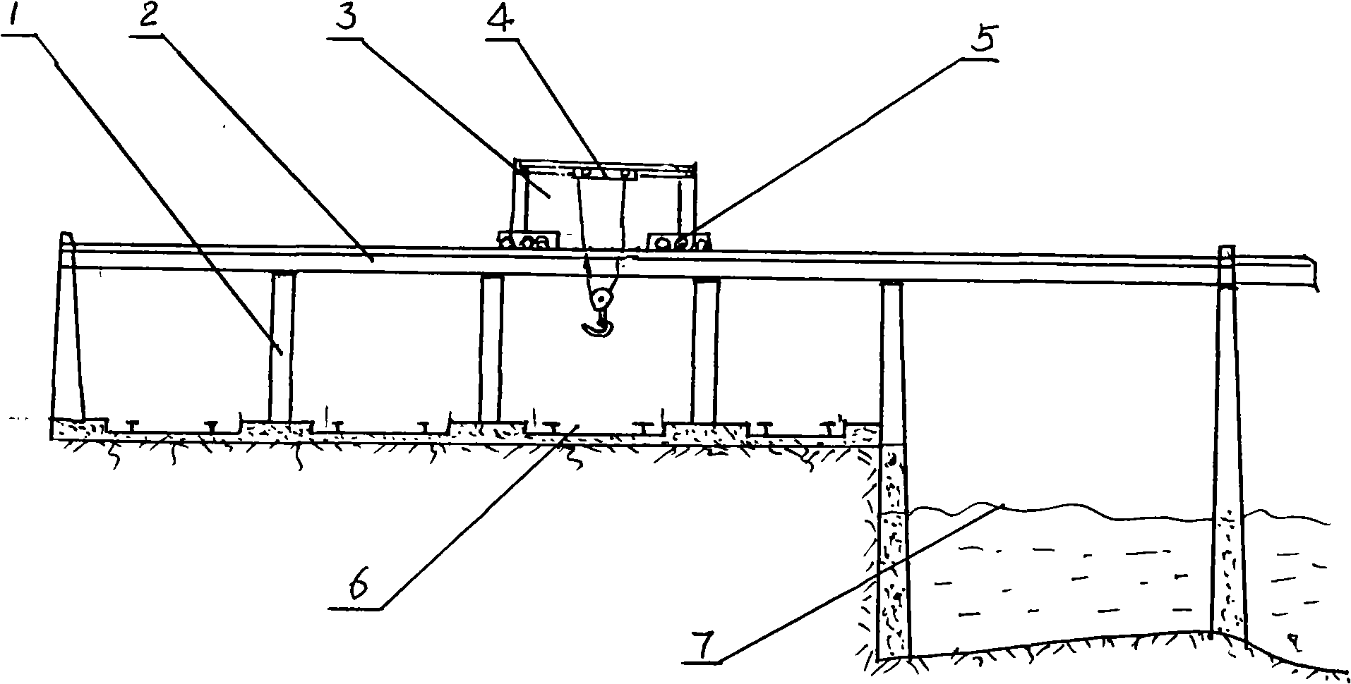
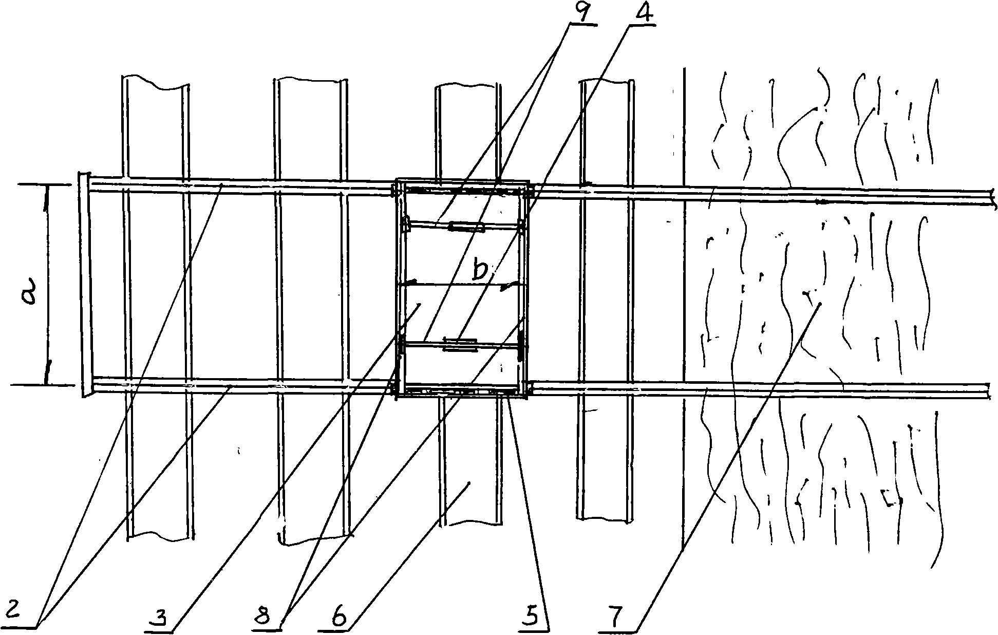
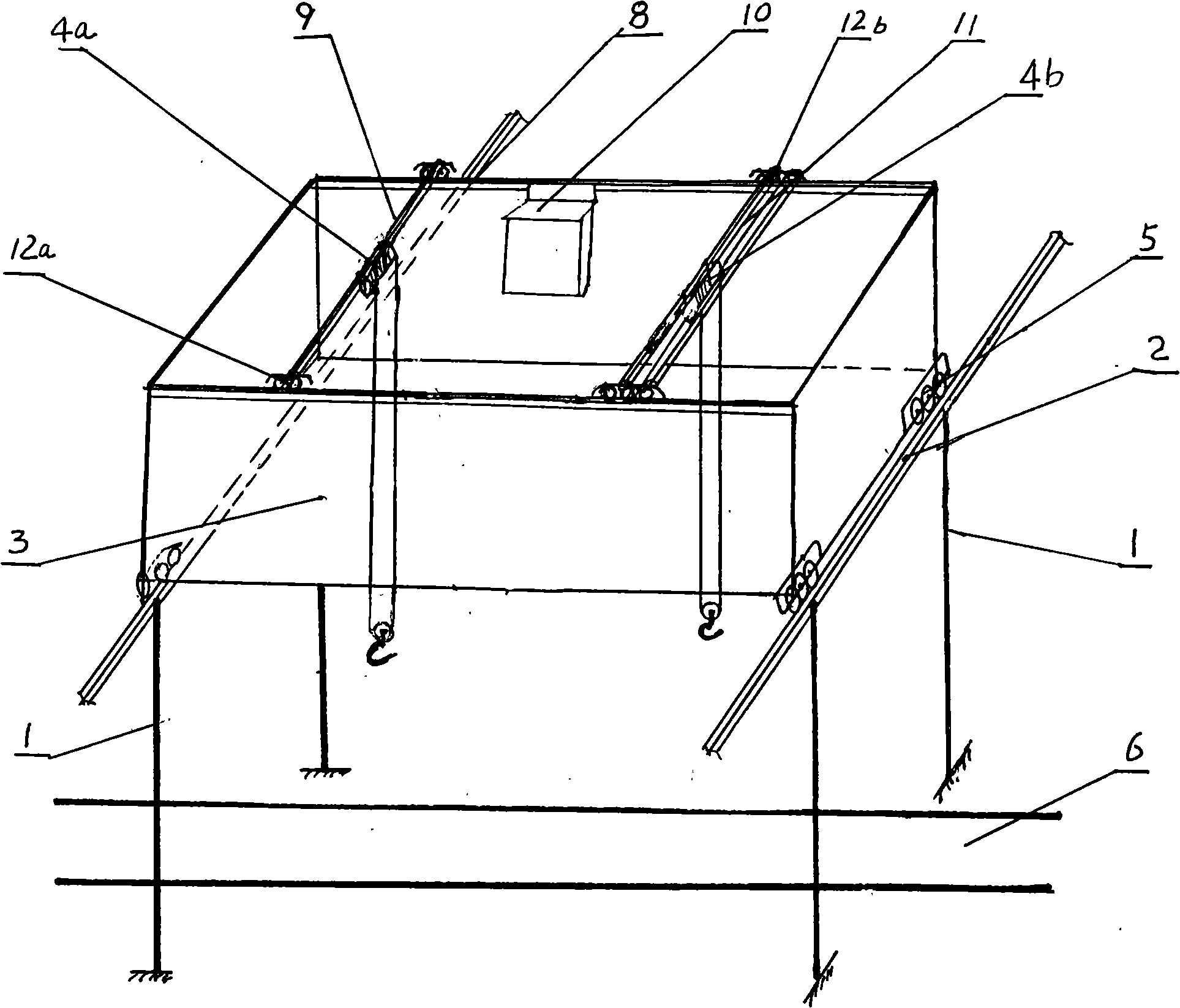
[0020] Such as figure 1 , figure 2 As shown, the double-girder viaduct crane of the present invention is composed of two rail girders 2 arranged in parallel, a large vehicle frame 3 composed of two rail beams 8, a large vehicle operating mechanism 5 fixed at both ends of the large vehicle frame 3, and arranged The track trolley 4 on the big vehicle frame 3, the hoisting mechanism (such as an electric hoist) fixed on the track trolley 4, and the operating room 10 and the electric control equipment fixed on the large vehicle frame 3 are formed. in:

[0021] Two parallel track main girders 2 are each supported by a row of support columns 1, spanning from the top of the railway 6 and extending to the ship berth 7 in the sea to form a viaduct structure; if it is only used for land goods such as trains and cars For loading and unloading, the viaduct structure extends over ...


PUM


Abstract

The present invention discloses a twin-beam viaduct type crane, which is mainly used for directly loading and unloading goods at long distance. The crane consists of two rail main beams, a large car frame, a large car operation mechanism, a small rail car, a lifting mechanism, an operating chamber, and a electronically controlled device, wherein the two rail main beams are arranged in parallel; the large car frame consists of two rail beams; the large car operation mechanism is fixed to the two ends of the large car frame; the small rail car is arranged on the large car frame; the lifting mechanism is fixed to the small rail car; and, the operating chamber and the electronically controlled device are fixed to the large car frame. The rail main beams span over a railway, and extend to a cargo work position. A rail longeron is arranged on the rail beam. Longeron operating mechanisms are respectively arranged on the two ends of the rail longeron. The small rail car is arranged on the rail longeron operating mechanism. The crane achieves the straight communication between the materials of a train and a ship. The middle operation is reduced and the handling speed is improved. The berthing of the chip can be far away from a port. The handling can be realized in the sea. The throughput of the port is increased. The crane is suitable for the handling of heavy materials and largetonnage ships.

Description

technical field [0001] The invention relates to a crane, in particular to a crane used for long-distance direct loading and unloading of goods. Background technique [0002] At present, the loading and unloading of cargo at ports and wharves is done by installing tower cranes on the coast. When unloading the ship, the cargo on the ship is hoisted and unloaded to the freight yard on the shore, and then loaded onto land transport vehicles such as trains and cars. When loading the ship, first unload the goods loaded by land transport vehicles such as trains and automobiles into the freight yard, and then hoist them one by one to the ship with a tower crane. Because the length of the boom of the tower crane is limited by mechanics, it can only unload ships that are docked on the shore, but cannot unload ships that are far away from the shore, which limits the throughput of the port, and it cannot directly load and unload trains, and an intermediate process is required, so mater...

Claims


Application Information

Patent Timeline
IPC IPC(8): B66C19/00
Inventor 徐西元
Owner 徐西元
Why Eureka
Try Eureka