All Fiber Optic Power Monitor
A technology of optical power and monitors, which is applied in optical fiber transmission, photometry, optical radiation measurement, etc., can solve the problems of high production cost and low photoelectric detection efficiency, and achieve low production cost, high transmission power processing capability, and low Effect of Return Loss
- Summary
- Abstract
- Description
- Claims
- Application Information
AI Technical Summary
Problems solved by technology
Method used
Image
Examples
Embodiment 1
[0031] The manufacturing method of the all-fiber optical power detector of the present invention is as follows:
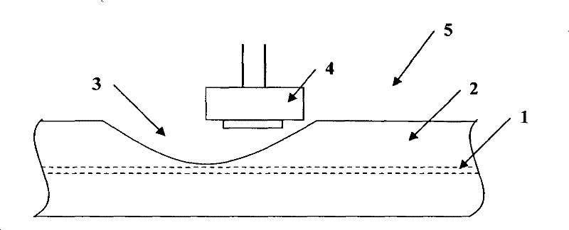
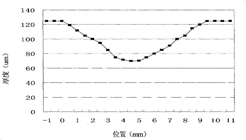
[0032] (1) Use the wheel-type optical fiber side polishing method to side-polish the cladding 2 of a section of optical fiber, and make a section of side polishing area 3 that is V-shaped along the optical fiber axis, as the optical fiber in the fiber core 1 Energy splitting area, the shape of the side polishing area is as image 3 As shown; the distance between the bottom of the V-shaped notch 3 and the fiber core 1 is 3um, and the length of the side polishing area is 9.5mm;
[0033] (2) Stretch the side polished optical fiber 5 and place it straight;
[0034] (3) placing the sensing plane of the photodetector 4 facing the V-shaped notch 3;
[0035] (4) Connect one end of the side-polished optical fiber 5 to the light source, and the other end to the optical power meter, and connect the electrode pin 7 of the photodetector 4 to the digital voltmeter to measure the...
Embodiment 2
[0040] Compared with Example 1, the difference lies in that the distance from the bottom of the V-shaped notch 3 to the fiber core 1 is 5um, and the length of the side polishing area is 5mm.
[0041] Experimental test results show that the insertion loss of the device of this embodiment is 0.35dB, the optoelectric responsivity (optoelectric responsivity) can reach 90mA / W, the polarization-dependent loss is 0.1dB, and the polarization stability (Polarization stability) is 0.3dB.
Embodiment 3
[0043] polished out Figure 5 The center is the large U-shaped side polishing area. The insertion loss of the side polishing optical fiber is 0.7dB. The same photodetector as in Example 1 is used to detect light energy, and the corresponding photoelectric responsivity is 2.66mA / W. This is because the middle part of the notch is relatively flat, and the flat part of the bottom portion disperses the leaked light energy, which is not conducive to the light energy collection of the photodetector.
PUM
 Abstract
Description
Claims
Application Information
 - Generate Ideas
- Intellectual Property
- Life Sciences
- Materials
- Tech Scout
- Unparalleled Data Quality
- Higher Quality Content
- 60% Fewer Hallucinations
Browse by: Latest US Patents, China's latest patents, Technical Efficacy Thesaurus, Application Domain, Technology Topic, Popular Technical Reports.
© 2025 PatSnap. All rights reserved.Legal|Privacy policy|Modern Slavery Act Transparency Statement|Sitemap|About US| Contact US: help@patsnap.com


