Method for obtaining time domain flat-top beam by once stimulated Brillouin scattering light limiting amplitude
A technology of stimulated Brillouin and flat-hat beams, which is applied in the field of nonlinear optics, can solve the problems of complex devices, large output energy loss, and the non-linear limiting mechanism cannot be applied to high-power laser system protection, etc., to achieve simple devices, Easy to control, effects with a wide range of wavelengths
- Summary
- Abstract
- Description
- Claims
- Application Information
AI Technical Summary
Problems solved by technology
Method used
Image
Examples
specific Embodiment approach 1
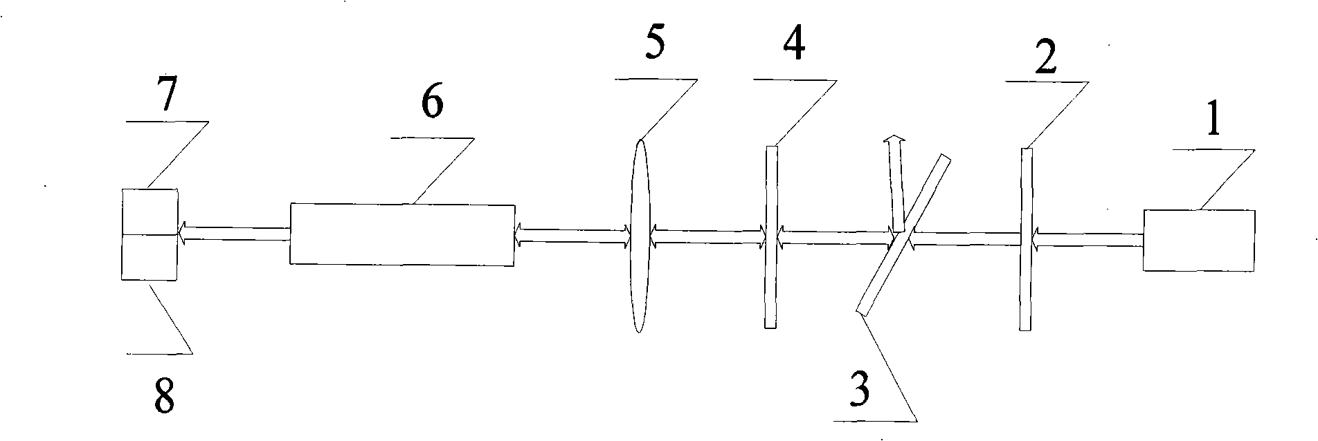
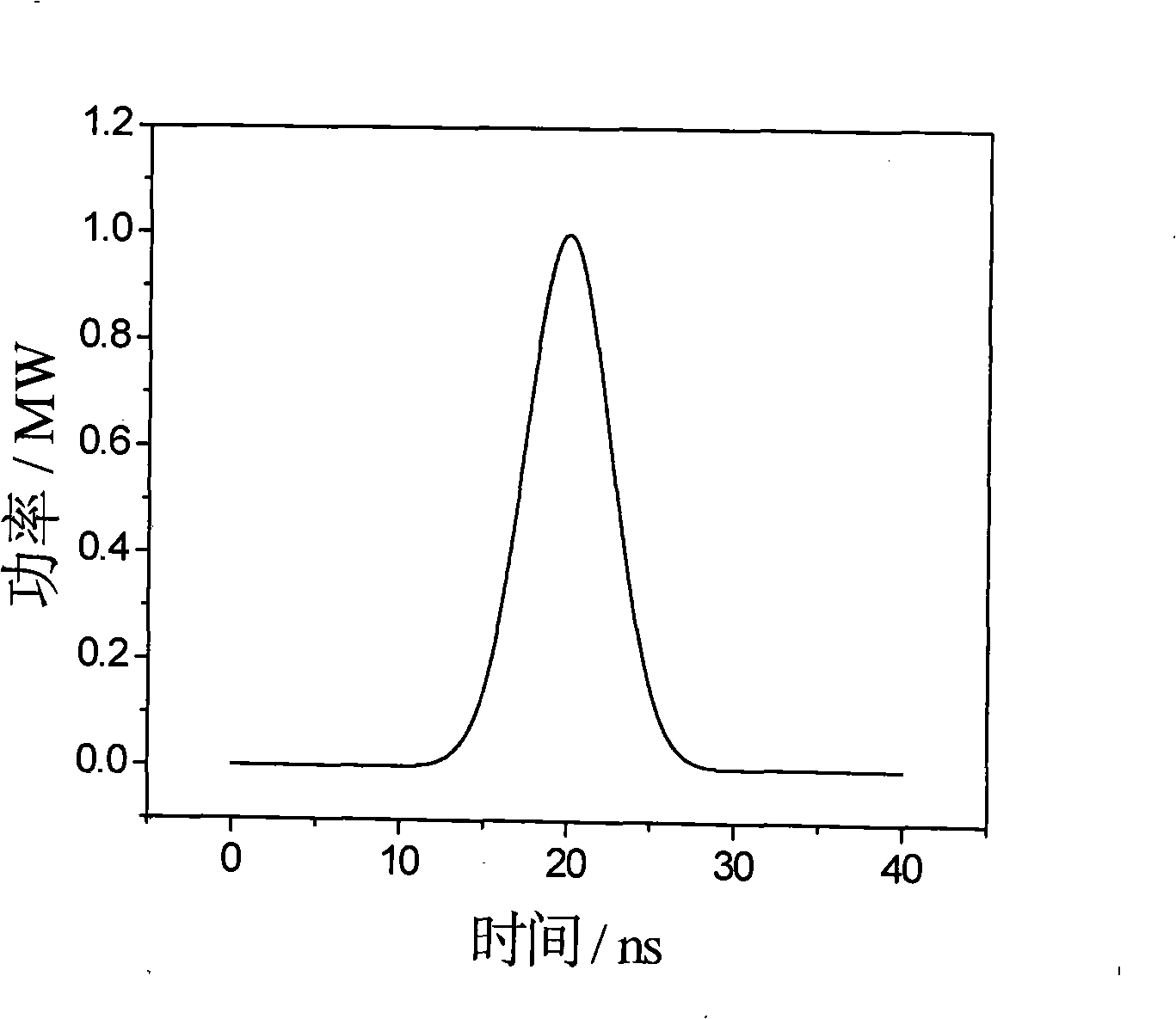
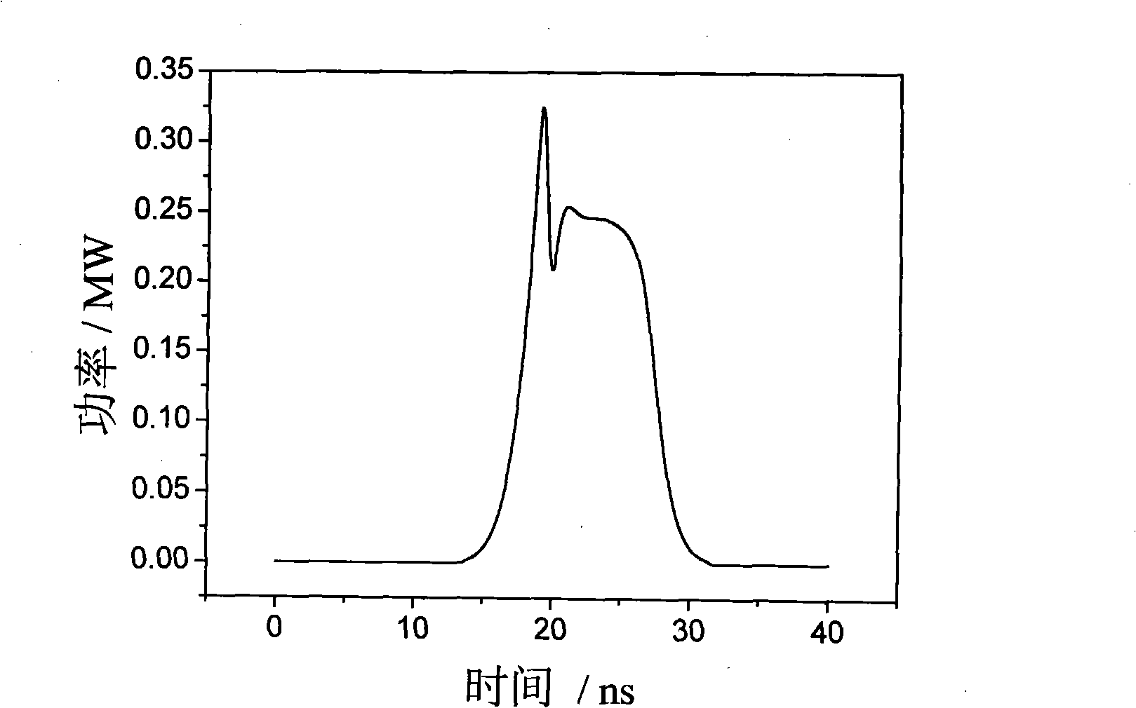
[0010] Specific implementation mode one: combine figure 1 This specific embodiment will be described. The primary stimulated Brillouin scattering system of this specific embodiment is composed of 1 / 2 wave plate 2, polarizer 3, 1 / 4 wave plate 4, lens 5 and oscillation pool 6, and realizes light limiting to obtain flat-top beam in time domain The method is as follows: the system inputs the s-polarized pump light to be transmitted through the 1 / 2 wave plate 2 to obtain the p-polarized pump light, and the p-polarized pump light is transmitted through the polarizer 3 and then enters the 1 / 4 wave plate 4. The circularly polarized pump light is obtained after the 1 / 4 wave plate 4 is transmitted, and the circularly polarized pump light is focused into the oscillation cell 6 through the lens 5, and generates excited Brillouin with the Brillouin medium in the oscillation cell 6. Scattering effect, the transmitted light generated by the scattering effect is the time-domain flat-top beam...
specific Embodiment approach 2
[0014] Embodiment 2: The difference between this embodiment and Embodiment 1 is that the s-polarized pump light input by the system is short-wavelength pump light, and the wavelength range is from ultraviolet pump light to infrared pump light.
[0015] The relationship between the phonon lifetime of the Brillouin medium and the wavelength of the pump light is τ=λ 2 / 4π 2 η (where τ is the phonon lifetime of the Brillouin medium, λ is the wavelength of the pump light, and η is the kinematic viscosity of the Brillouin medium), it can be seen that the phonon lifetime of the Brillouin medium is proportional to the wavelength of the pump light Therefore, the shorter the wavelength of the pump light, the shorter the phonon lifetime of the Brillouin medium, the faster the phonon field is established, the more thoroughly the front energy of the pump light is transferred to the Stokes field, and the obtained Stimulated Brillouin scattered light clipping time domain pulse waveform is f...
specific Embodiment approach 3
[0018] Embodiment 3: The difference between this embodiment and Embodiment 1 is that the kinematic viscosity of the Brillouin medium ranges from 3.0 cSt to 18.0 cSt. The preferred range of the kinematic viscosity of the Brillouin medium in this specific embodiment is between 4.0 cSt and 15.0 cSt.
[0019] The relationship between the phonon lifetime of the Brillouin medium and its kinematic viscosity is τ=λ 2 / 4π 2η (where τ is the phonon lifetime of the Brillouin medium, λ is the wavelength of the pump light, and η is the kinematic viscosity of the Brillouin medium), it can be seen that the phonon lifetime of the Brillouin medium is inversely proportional to its kinematic viscosity, so The greater the kinematic viscosity of the Brillouin medium, the shorter the phonon lifetime, the faster the phonon field is established, the more thorough the energy transfer from the front of the pump light to the Stokes field, and the obtained stimulated Brillouin scattered light The flatt...
PUM
| Property | Measurement | Unit |
|---|---|---|
| Wavelength | aaaaa | aaaaa |
| Kinematic viscosity | aaaaa | aaaaa |
| Kinematic viscosity | aaaaa | aaaaa |
Abstract
Description
Claims
Application Information
 - Generate Ideas
- Intellectual Property
- Life Sciences
- Materials
- Tech Scout
- Unparalleled Data Quality
- Higher Quality Content
- 60% Fewer Hallucinations
Browse by: Latest US Patents, China's latest patents, Technical Efficacy Thesaurus, Application Domain, Technology Topic, Popular Technical Reports.
© 2025 PatSnap. All rights reserved.Legal|Privacy policy|Modern Slavery Act Transparency Statement|Sitemap|About US| Contact US: help@patsnap.com


