Eureka AIR delivers breakthrough ideas for toughest innovation challenges, trusted by R&D personnel around the world.

Wave guide structure of microwave oven

A waveguide structure and microwave oven technology, applied in the field of microwave ovens, can solve the problems of magnetron damage, high microwave reflection coefficient, magnetron heating, etc., and achieve the effect of improving feedback aggregation and prolonging service life

Inactive Publication Date: 2008-12-17
LG ELECTRONICS (TIANJIN) APPLIANCES CO LTD
View PDF0 Cites 0 Cited by
  • Summary
  • Abstract
  • Description
  • Claims
  • Application Information

AI Technical Summary

Problems solved by technology

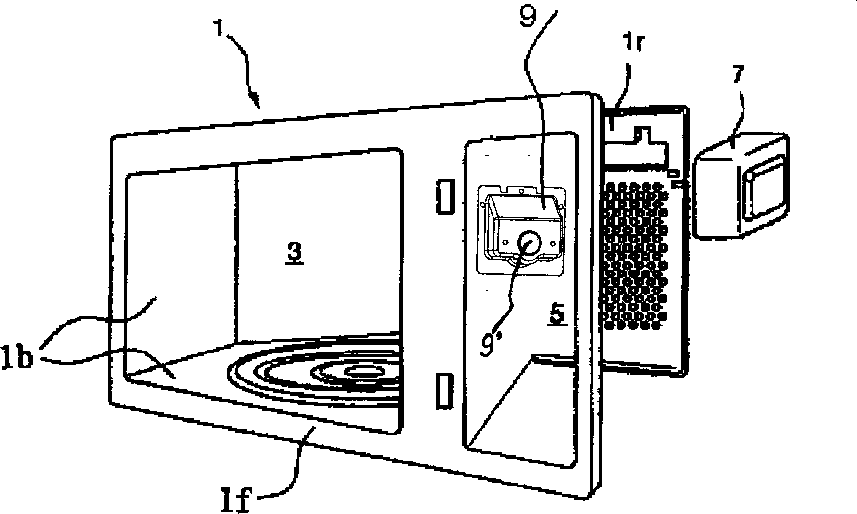
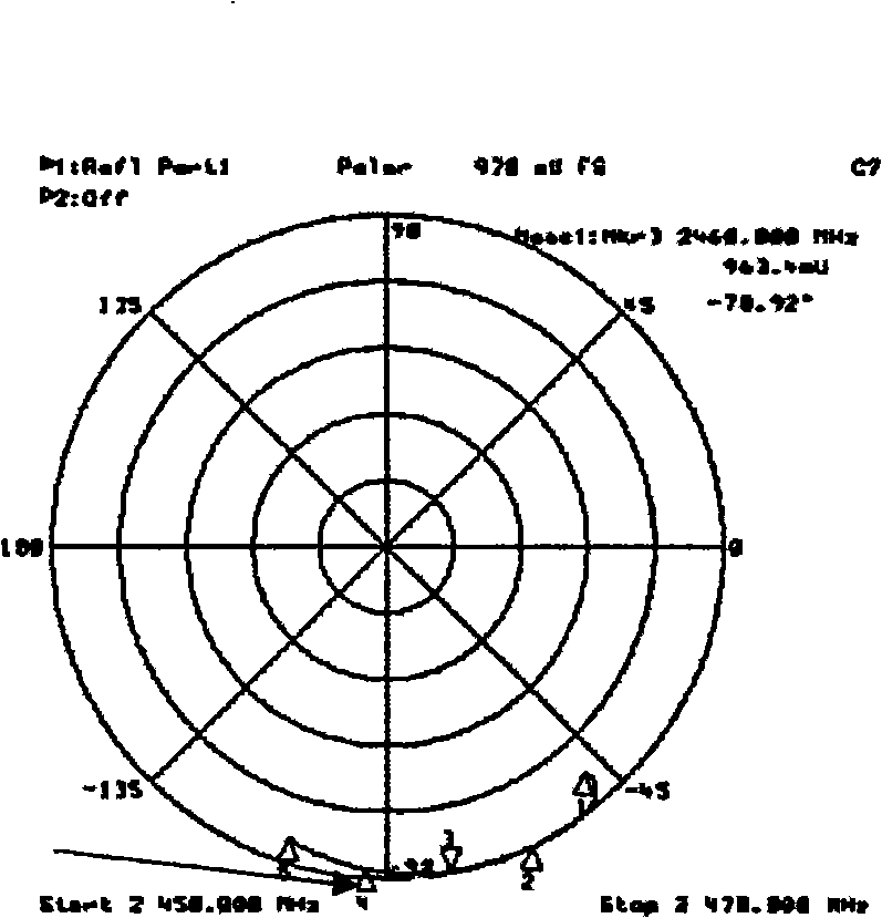
However, the existing waveguide has the following disadvantages: when the microwave is irradiated in the waveguide 9 through the antenna, it can be seen from the impedance matching diagram that the reflection coefficient of the microwave is relatively large, close to 1, and a lot of microwave energy will be reflected back to the waveguide 9. The magnetron makes the magnetron heat up, which can easily lead to the damage of the magnetron

Method used


Image

  • Wave guide structure of microwave oven
  • Wave guide structure of microwave oven
  • Wave guide structure of microwave oven

Examples


Embodiment Construction

[0016] The technical characterictic that the present invention is identical with prior art is no longer described in detail below:

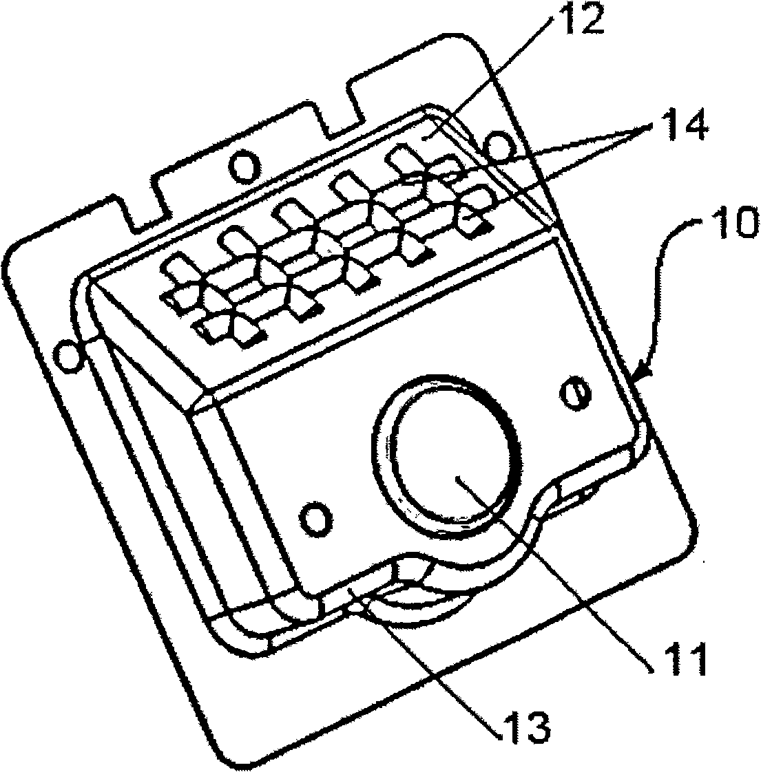
[0017] Such as image 3 and Figure 4 As shown, the waveguide structure of the microwave oven of the present invention includes a magnetron insertion port 11 for inserting the antenna of the magnetron into the waveguide 10, an inclined top wall 12 and a U-shaped lower wall 13, and the U-shaped lower wall Wall 13 is shorter than inclined top wall 12, and is parallel to antenna, and waveguide 10 is formed with the passageway that guides microwave in it, makes the microwave that produces on the magnetron of electric control room can pass to cooking through the outlet of waveguide. Inside the chamber, the inclined top wall 12 of the waveguide 10 is provided with a groove 14, the groove 14 can reflect the microwave, and the reflection coefficient is about 0.75 according to the schematic diagram of the microwave reflection impedance. The grooves 14 a...


PUM


Abstract

The invention discloses a microwave oven, in particular to a waveguide tube structure for a microwave oven capable of guiding microwave into a cooking chamber. The technical problem to be solved is that the invention provides a waveguide structure for microwave oven with simple structure and capable of reducing microwave reflection coefficient. The waveguide structure of the microwave oven comprises a magnetron insert slot, an inclined top wall, a U-shaped lower wall, wherein the U-shaped lower wall is shorter than the inclined top wall and is parallel to an antenna; and grooves are formed on the inclined top wall. The grooves arranged horizontally and vertically on the inclined top wall of the waveguide tube can prevent a portion of microwave energy from returning to the magnetron, thus effectively improving the heat feedback and aggregation of the magnetron, and prolonging the service life of the magnetron.

Description

technical field [0001] The present invention relates to a microwave oven, and more particularly to a structure of a microwave waveguide for guiding microwaves into a cooking chamber. Background technique [0002] Microwave is a kind of high-frequency wave, which changes at a speed of 2.4 billion times per second, causing high-speed motion of water molecules, causing water molecules to rub against each other to generate heat, in order to achieve the purpose of heating food, and can heat the inside and outside of the food at the same time, so Microwaves are widely used in the cooking of many kinds of food. [0003] Microwaves are used in the microwave oven to heat food, and the magnetron generates microwaves, which are introduced into the cooking chamber through wave guides. Such as figure 1 As shown, the cavity 1 plays a role as a frame inside the microwave oven, and a cooking chamber 3 for cooking is formed inside the cavity 1, and an electric control room 5 is arranged on...

Claims


Application Information

Patent Timeline
Patent Type & Authority Applications(China)
IPC IPC(8): F24C7/02F24C7/06
Inventor 王磊
Owner LG ELECTRONICS (TIANJIN) APPLIANCES CO LTD
Why Eureka
Eureka Blog
Learn More