
Image processing device and method, image forming device and image processing system

An image processing device and image generation technology, applied in the field of image processing, can solve the problems of inability to recognize high-precision format, decrease in determination accuracy, and change in recognition results, etc.

Inactive Publication Date: 2008-12-10
SHARP KK
View PDF3 Cites 13 Cited by
  • Summary
  • Abstract
  • Description
  • Claims
  • Application Information

AI Technical Summary

Problems solved by technology

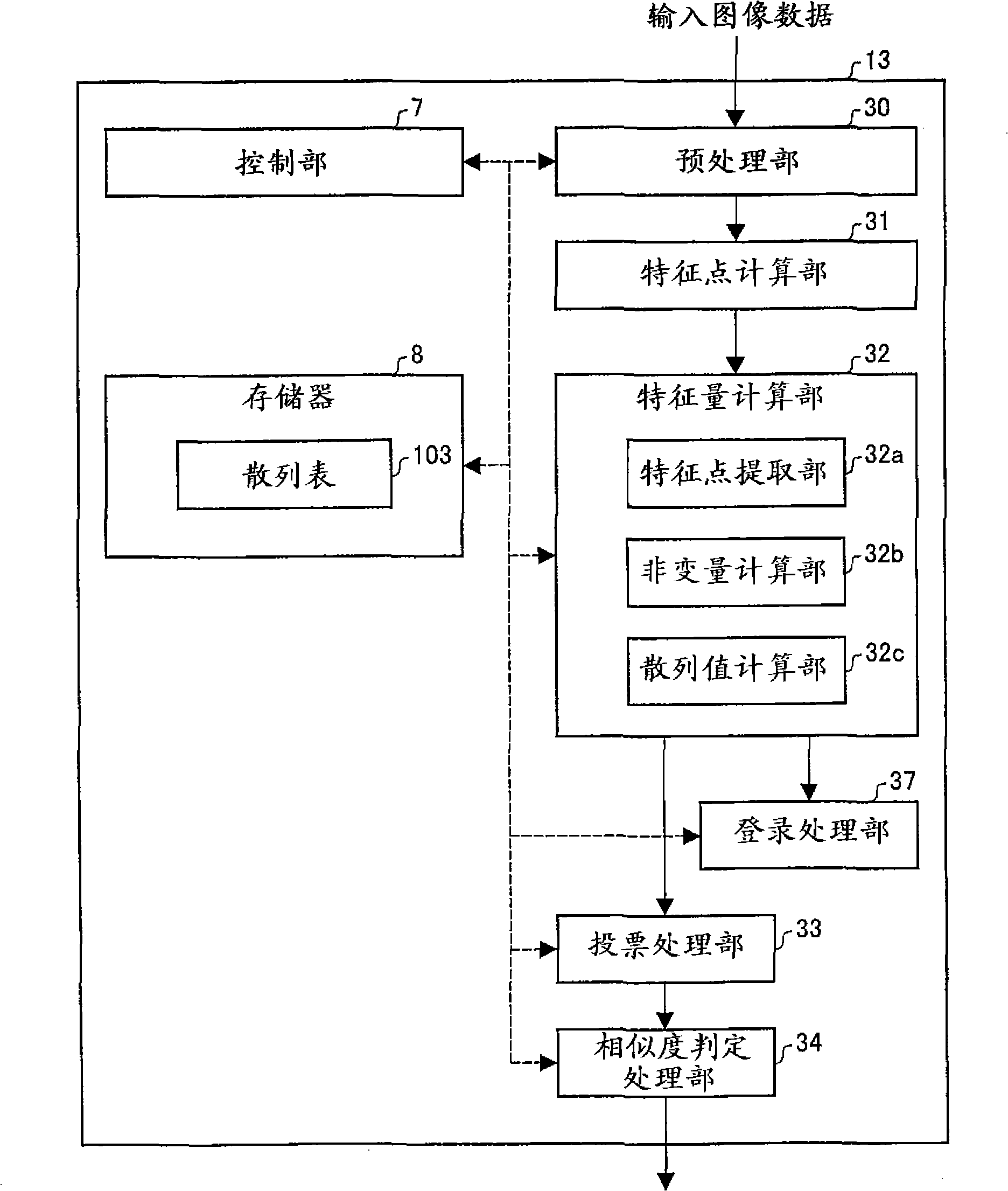
[0006] However, in the techniques of the above-mentioned Patent Documents 1 and 2, there is a problem that feature points cannot be extracted with high accuracy when the input image data is subjected to processing such as reduction and enlargement.
[0007] For example, in the technology of Patent Document 1, the recognition results of characters, character strings, frames, etc. are changed due to the influence of enlargement, reduction, etc., so format recognition cannot be performed with high accuracy.
[0008] Moreover, in the technology of Patent Document 2, due to the influence of enlargement and reduction, etc., the center of gravity of words in English documents, the center of gravity of connected components of black pixels, the closed space of Chinese characters, and specific parts that repeatedly appear in images, etc. The extraction results have changed, so the accuracy of the file comparison results has decreased
[0009] In addition, when extracting feature points from an image containing handwritten characters (for example, an image written by handwriting in a document printed with a predetermined font), the shape of the handwritten character and the font registered in the image processing device The dissimilarity is high, which is inherently prone to misjudgment. In addition, in the technologies of the above-mentioned patent documents 1 and 2, the judgment accuracy is reduced due to the influence of the above-mentioned enlargement, reduction, etc., so misjudgment is particularly prone to occur.

Method used


Image

  • Image processing device and method, image forming device and image processing system
  • Image processing device and method, image forming device and image processing system
  • Image processing device and method, image forming device and image processing system

Examples


Embodiment approach 1

[0047] Next, an embodiment of the present invention will be described. However, in this embodiment, an example in which the present invention is applied to a digital color multi-function printer (MFP: Multi-Function Printer) will be described.

[0048] (1-1. Structure of digital color multifunction machine 1)

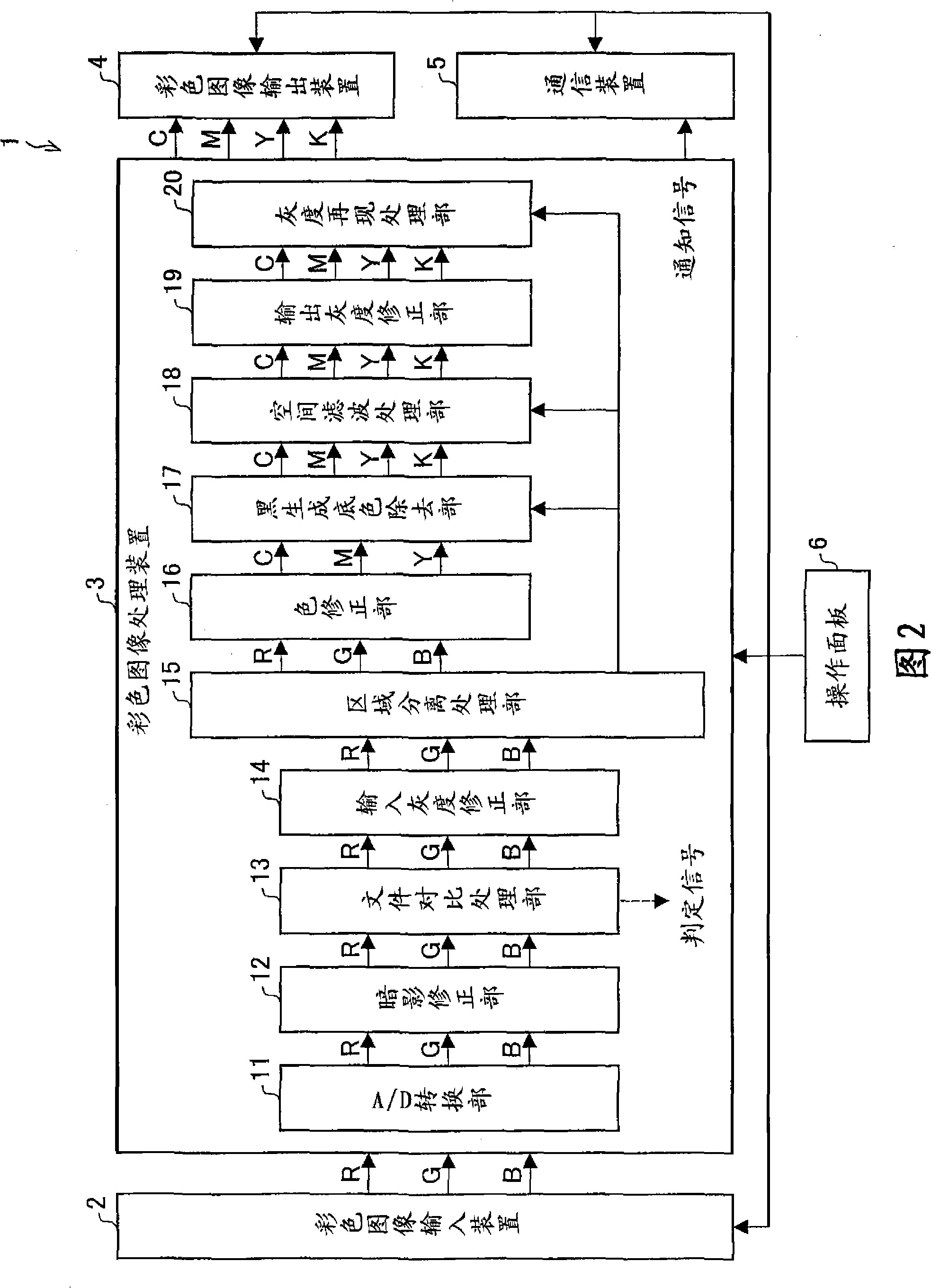
[0049] FIG. 2 is a block diagram showing a schematic configuration of a digital color multifunction peripheral (image processing device, image forming device, image reading device) 1 according to this embodiment. The digital color multifunction machine 1 has a copy function, a print function, a facsimile transmission function, a scan function, a scan to e-mail function, and the like.

[0050] As shown in FIG. 2 , the digital color multifunction peripheral 1 has a color image input device 2 , a color image processing device 3 , a color image output device 4 , a communication device 5 , and an operation panel 6 .

[0051] The color image input device (image reading devi...


PUM


Abstract

An image processing device and method, an image forming device, an image processing device are provided. The image processing device includes a pattern detection process section for extracting a partial image made of pixels including a target pixel from input image data; a displaced image generation section for generating a self-displaced image by displacing at least a part of the partial image through a predetermined method; and a matching test determination section for determining whether an image pattern included in the partial image matches an image pattern included in the self-displaced image or not. When the matching test determination section determines that the matching exists, a target pixel in the partial image or a block made of pixels including the target pixel is regarded as a feature point. Consequently, even when image data is subjected to a process such as enlarging and reducing, it is possible to extract a feature point that properly specifies the image data regardless of the enlarging / reducing process.

Description

technical field [0001] The present invention relates to an image processing device, an image forming device, an image processing system, and an image processing method including a feature amount calculation unit that extracts a feature amount of image data. Background technique [0002] Conventionally, various techniques have been proposed that compare input image data obtained by scanning a document image with a scanner with a registered image registered in advance to determine the degree of similarity between the two. [0003] As a similarity determination method, for example, a method of extracting a keyword from a character image using OCR (Optical Character Reader) and performing a matching method, and a method of extracting and comparing features of a line included in an image have been proposed. Wait. [0004] In addition, in Patent Document 1 (Japanese Laid-Open Patent Publication No. Hei 8-255236 (publication date: October 1, 1996)), a method for recognizing charac...

Claims


Application Information

Patent Timeline
IPC IPC(8): G06K9/00G06K9/62H04N1/387
Inventor 早崎真
Owner SHARP KK
Learn More