
Electrostatic driven F-P cavity MEMS wavelength tunable filter

An electrostatic drive, electrostatic drive technology, applied in the direction of instruments, nonlinear optics, optics, etc., can solve the problems of wide beam drop, filter efficiency selection, light utilization rate drop, thickness inconsistency, etc., to achieve the effect of improving filter efficiency

Inactive Publication Date: 2010-11-03
INST OF OPTICS & ELECTRONICS - CHINESE ACAD OF SCI
View PDF0 Cites 0 Cited by
  • Summary
  • Abstract
  • Description
  • Claims
  • Application Information

AI Technical Summary

Problems solved by technology

However, the disadvantage of the F-P cavity MEMS wavelength tunable filter with this structure is: when there is a potential difference between the front and rear cavity surfaces, the front cavity surface is bent, so that the thickness of the air gap between the front and rear cavity surfaces is inconsistent at different positions. The thickness of the air gap is the smallest, so that the light reflected from the front and rear cavity surfaces is no longer parallel light, and the interference fringes of the reflected light are no longer parallel, which will lead to a decrease in filtering efficiency and utilization of selected light. Wider beams drop more

Method used


Image

  • Electrostatic driven F-P cavity MEMS wavelength tunable filter
  • Electrostatic driven F-P cavity MEMS wavelength tunable filter
  • Electrostatic driven F-P cavity MEMS wavelength tunable filter

Examples


Embodiment Construction

[0018] The present invention will be described in detail below in conjunction with the accompanying drawings and specific embodiments.

[0019] In this embodiment, an electrostatically driven F-P cavity MEMS wavelength tunable filter with a radius of 100 μm in both the front cavity surface and the rear cavity surface is taken as an example, and the present invention is described in detail with reference to the accompanying drawings.

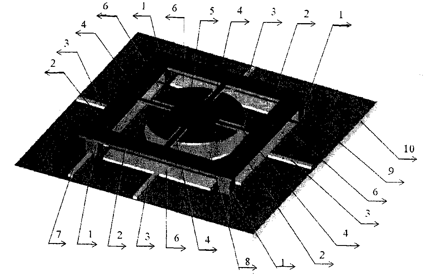
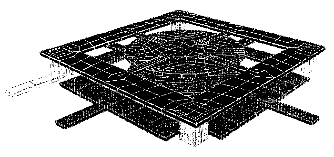
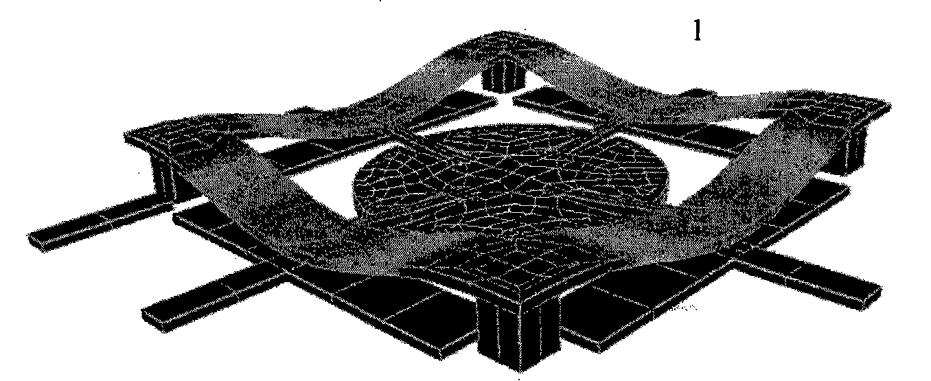
[0020] figure 1 It is a three-dimensional schematic diagram of an electrostatically driven F-P cavity MEMS wavelength tunable filter of this embodiment; An insulating layer 9 is grown on it to separate the silicon substrate 10 from the electrostatically driven F-P cavity MEMS wavelength tunable filter, and the material of the insulating layer 9 can be silicon dioxide or silicon nitride; the electrostatically driven F-P cavity MEMS wavelength of the present embodiment The F-P cavity in the adjustable filter is located in the center of the whole s...


PUM


Abstract

The preset invention discloses a static-driven F-P cavity MEMS tunable wavelength filter which comprises an F-P cavity. The F-P cavity MEMS tunable wavelength filter is characterized in that the perimeter of the F-P cavity is connected with four static drivers; wherein, the upper electrode panels of the four static drivers are respectively connected with the front cavity face of the F-P cavity through four connecting rods, and the lower electrode panels of the four static drivers are fixed on the same plane as the rear cavity panel of the F-P cavity; the front cavity face of the static-drivenF-P cavity MEMS tunable wavelength filter of the present invention can be moved horizontally under the driving of the static drivers; therefore, the reflected light of the front cavity face and the rear cavity face are parallel to increase the filtering efficiency and the light use ratio of the F-P cavity MEMS wavelength tunable filter. The F-P cavity MEMS wavelength tunable filter of the presentinvention has the advantages of small volume, low energy consumption, simple structure and easy manufacture. The F-P cavity MEMS wavelength tunable filter can be widely used in the optical fiber communication systems.

Description

technical field [0001] The invention relates to the technical field of micro-opto-electromechanical systems, in particular to an electrostatically driven F-P cavity (Fabry-Perot cavity) MEMS wavelength tunable filter suitable for optical fiber communication systems. Background technique [0002] In the field of wavelength tunable filters, electrostatically driven MEMS wavelength tunable filters have the advantages of small size, low energy consumption, fast response, low driving voltage, and good compatibility with integrated circuits, and are widely used in optical fiber communication systems. favor. The existing electrostatically driven MEMS wavelength tunable filters all adopt F-P cavity structure, the front cavity surface is a thin film with both reflection and transmission, and the periphery is fixed; the rear cavity surface is fixed and is a total reflection surface. When a driving voltage is applied between the front and rear cavity surfaces, the front cavity surface...

Claims


Application Information

Patent Timeline
Patent Type & Authority Patents(China)
IPC IPC(8): G02F1/21
Inventor 姚军王大甲胡放荣邱传凯
Owner INST OF OPTICS & ELECTRONICS - CHINESE ACAD OF SCI
Learn More