
Heat-transferring die, manufacturing process and heat-transferring manufacturing process

A thermal transfer film and manufacturing process technology, applied in the field of thermal transfer film and its manufacturing process and thermal transfer manufacturing process, can solve the problem of small, applied in clothes, cloth bags, hats, pillows, mugs, porcelain Disks, tiles, watch cases, mouse pads, coasters, hanging calendars, medals, pennants, work cards, house numbers, mirror boxes, metal jugs, etc.

Inactive Publication Date: 2008-12-10
白洪城
View PDF0 Cites 32 Cited by
  • Summary
  • Abstract
  • Description
  • Claims
  • Application Information

AI Technical Summary

Problems solved by technology

The current thermal transfer film is made by screen printing, and the pattern area is small. It is used in clothes, cloth bags, hats, pillows, mugs, porcelain plates, ceramic tiles, watch cases, mouse pads, coasters, hanging calendars, and medals. , pennants, work cards, door plates, mirror boxes, metal wine jugs... and other commodities are acceptable, but if they are to be applied to large-scale building materials, such as the transfer printing of colored corrugated boards, large glass plates or entire tiles, etc., technically still pending breakthrough

Method used


Image

  • Heat-transferring die, manufacturing process and heat-transferring manufacturing process
  • Heat-transferring die, manufacturing process and heat-transferring manufacturing process
  • Heat-transferring die, manufacturing process and heat-transferring manufacturing process

Examples


Embodiment Construction

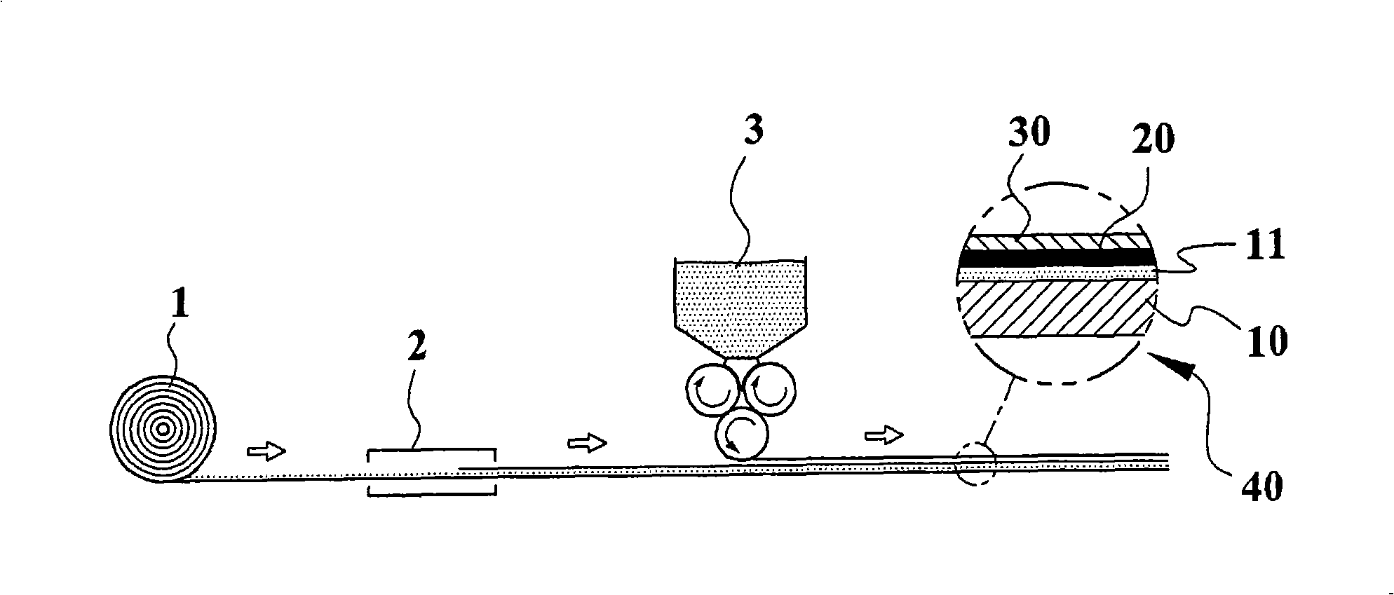
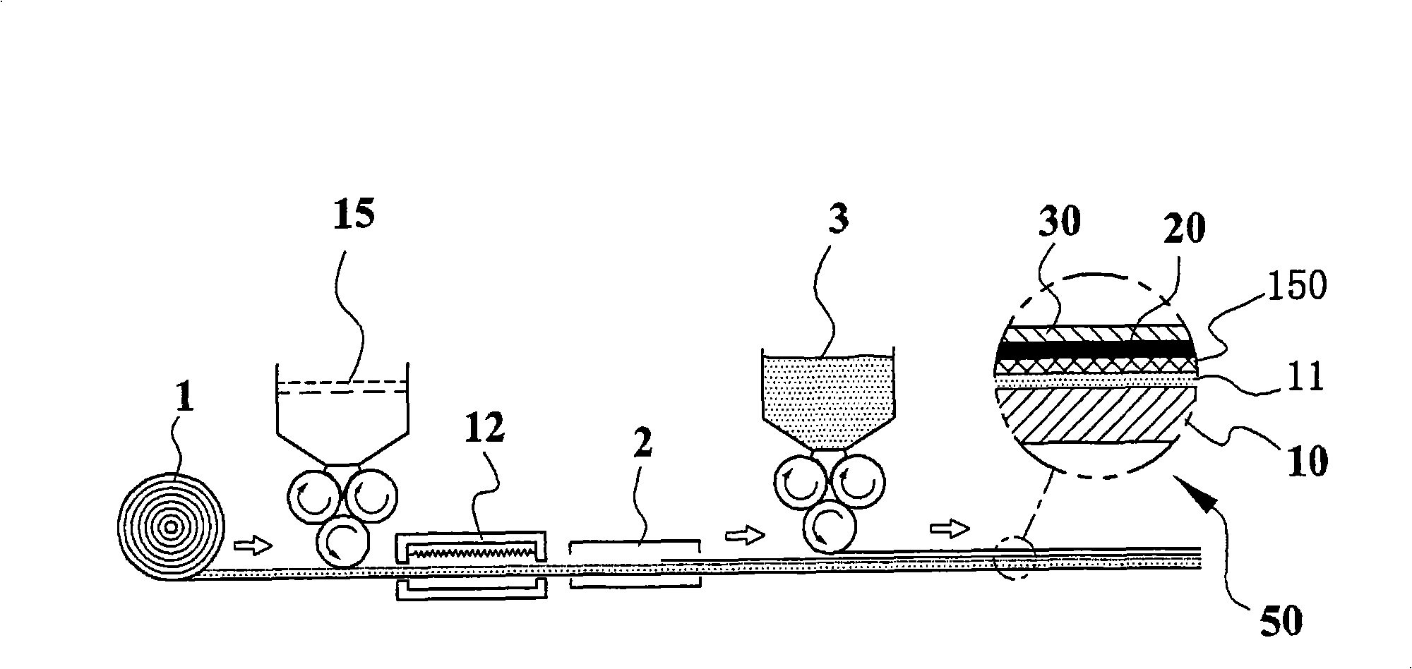
[0030] Such as figure 1 The schematic diagram of the embodiment of the structure and manufacturing process steps of the thermal transfer film 40 of the present invention is shown, including:

[0031] 1. The preparation step is to prepare a high-temperature-resistant film 1 with a release agent coating on its surface, so that it contains at least a high-temperature-resistant film 10 and a release agent coating 11;

[0032] 2. The printing step, using a printing device 2 to print a high temperature resistant ink layer 20 on the surface of the release agent coating 10; and

[0033] 3. Coating step, using a coating device 3 to coat a high-temperature-resistant heat-reactive hot-melt adhesive 30 on the high-temperature-resistant ink layer 20, thereby forming a high-temperature-resistant heat-reactive hot-melt adhesive on the high-temperature resistant ink layer 20 layer.

[0034] Through the above steps, the thermal transfer film 40 with a large area and unlimited length can be r...


PUM


Abstract

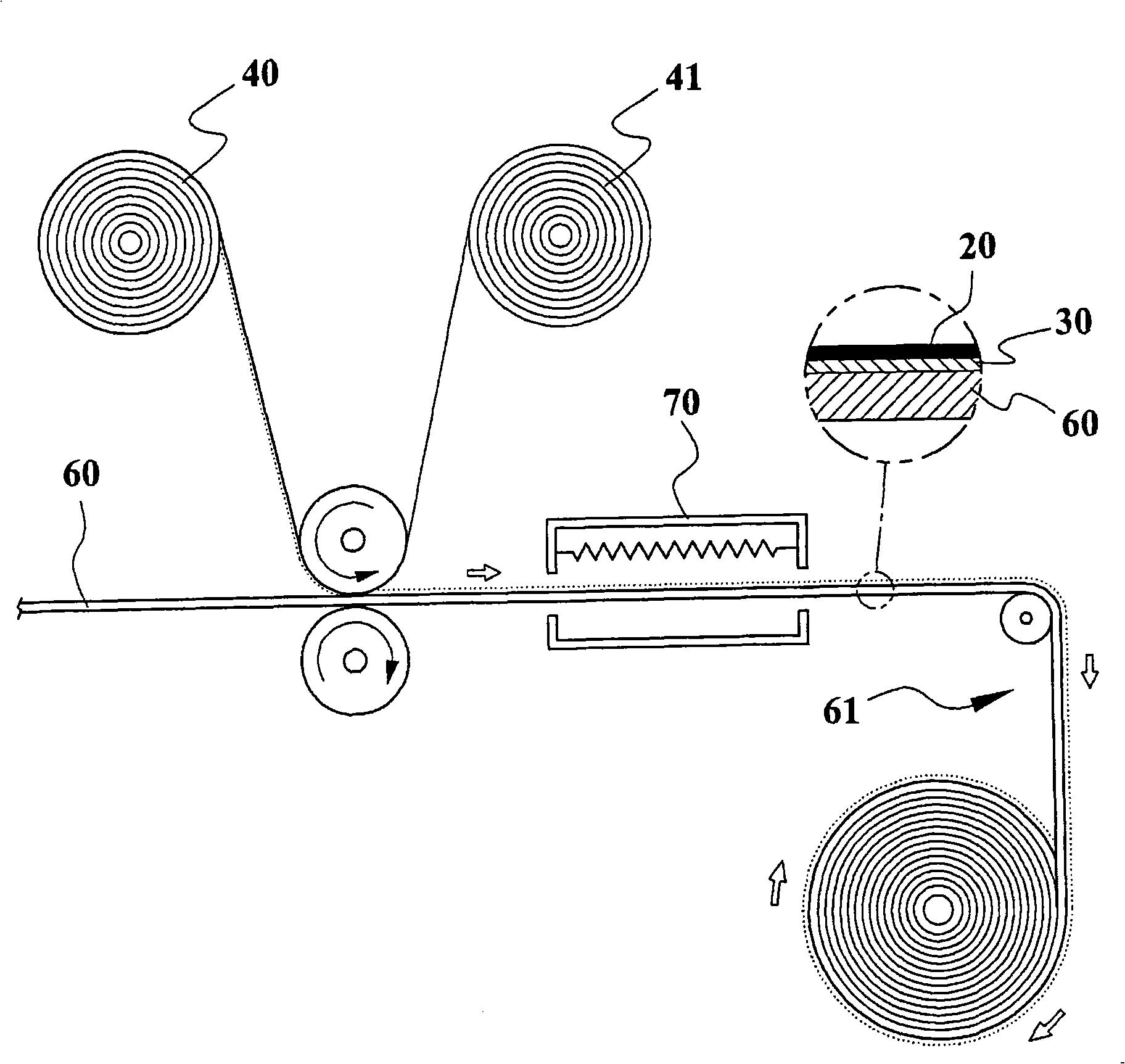
A thermal transfer film which can carry out continuous thermal transfer in a large area directly forms a single-color or colorful printing pattern with excellent layer film structure intensity on the transferred surfaces of various metal, glass or ceramic substances. The manufacturing technique of the thermal transfer film includes that printing is carried out a whole volume of continuous plastic film material or paper material the surface of which comprises a release layer with the ink of a high temperature-resistance dye by a gravure printer to generate the ink layer of the high temperature-resistance dye; the layer of a high temperature-resistance thermal reaction hot melt adhesive is coated on the surface of the ink layer of the high temperature-resistance dye. The thermal transfer steps include: a. the steps of degreasing, dust removing, purifying of the transferred surface of a substance; b. the step of fictitiously fixing: the thermal transfer film comprising the ink of the high temperature-resistance dye and the layer of the high temperature-resistance thermal reaction hot melt adhesive are taken to carry out thermal transfer on the transferred surface of the step a to lead the ink layer of the high temperature-resistance dye and the layer of the high temperature-resistance thermal reaction hot melt adhesive to be fictitiously fixed on the transferred surface; c. the step of roasting for leading the ink of the high temperature-resistance dye and the layer of the high temperature-resistance thermal reaction hot melt adhesive to be firmly combined with the transferred surface.

Description

technical field [0001] The invention relates to a large-area, continuous thermal transfer thermal transfer film and its manufacturing process and thermal transfer manufacturing process, which is to print a high-temperature-resistant pigment ink on a continuous roll by using printing equipment. In the permanent heat transfer film, use the heat transfer equipment to make the high temperature resistant pigment ink falsely fixed on the transfer surface of the article, and finally use the baking equipment to firmly combine the high temperature resistant pigment ink with the transfer surface of the article. Background technique [0002] It is still an unachievable research and development goal to use printing equipment to quickly and large-scale produce text or patterns with rich colors, accurate color rendering and high resolution on non-absorbent surfaces such as various metals, glass or ceramics. [0003] Comparing several printing methods currently known with the present inven...

Claims


Application Information

Patent Timeline
IPC IPC(8): B41M5/035B41M3/12B44C1/17
Inventor 白洪城
Owner 白洪城
Learn More