
Arrangement for processing dust

一种粉尘、除尘器的技术,应用在除尘器,凿岩台车领域,能够解决缓慢操作速度等问题

Inactive Publication Date: 2008-12-03
SANDVIK MINING & CONSTR OY
View PDF1 Cites 14 Cited by
  • Summary
  • Abstract
  • Description
  • Claims
  • Application Information

AI Technical Summary

Problems solved by technology

The problem with this unloading device is its slow speed of operation

Method used


Image

  • Arrangement for processing dust
  • Arrangement for processing dust
  • Arrangement for processing dust

Examples


Embodiment Construction

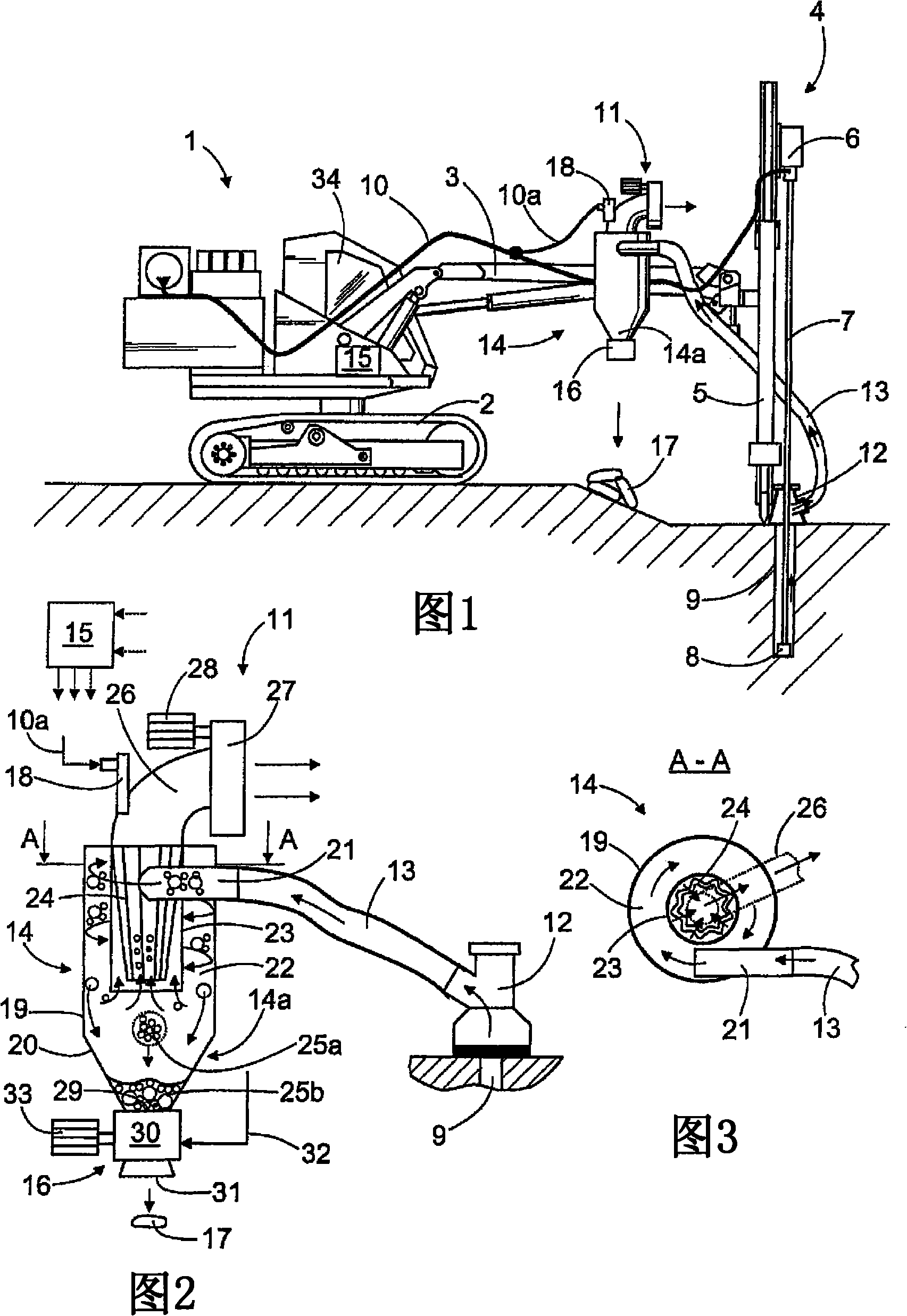
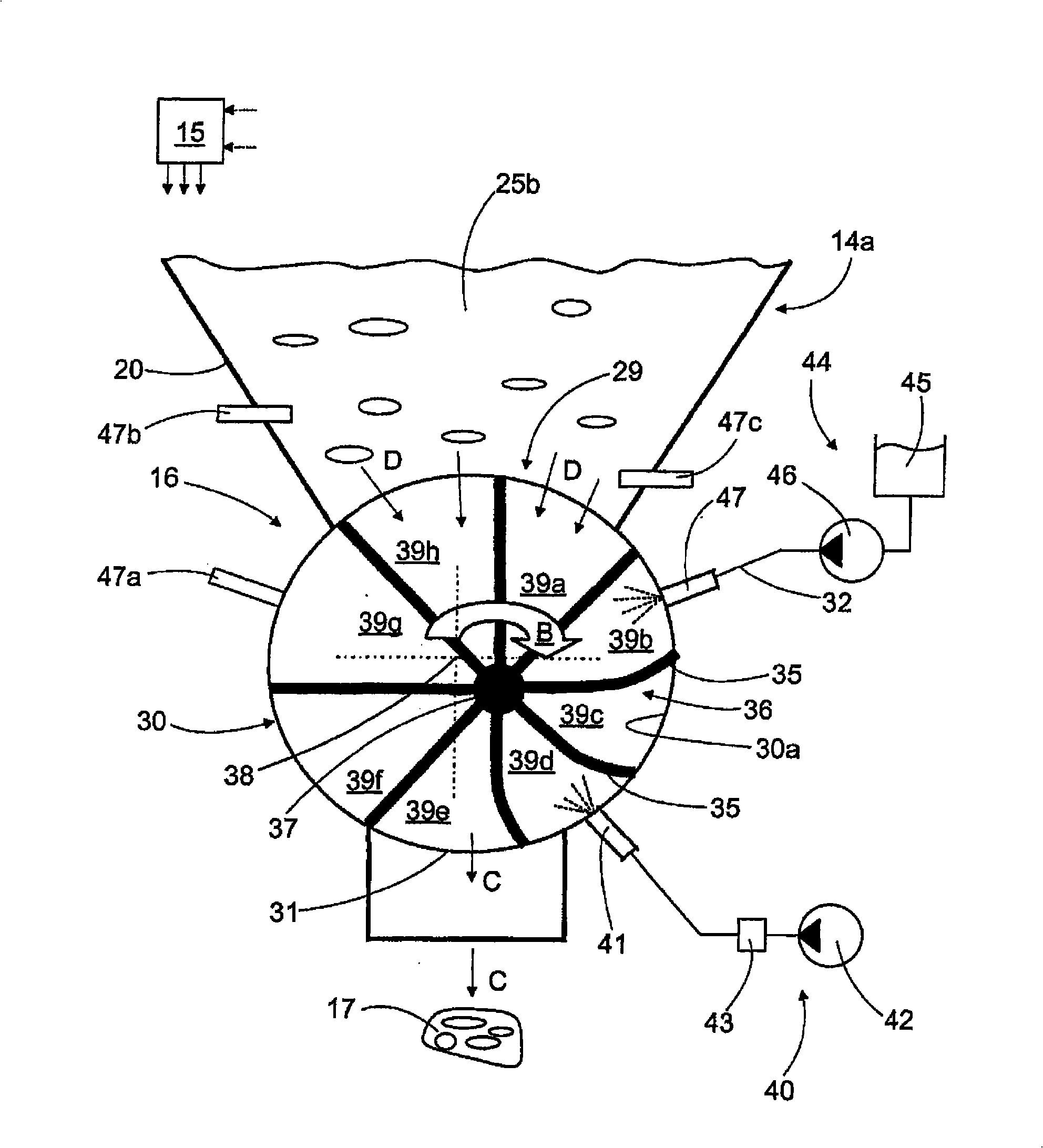
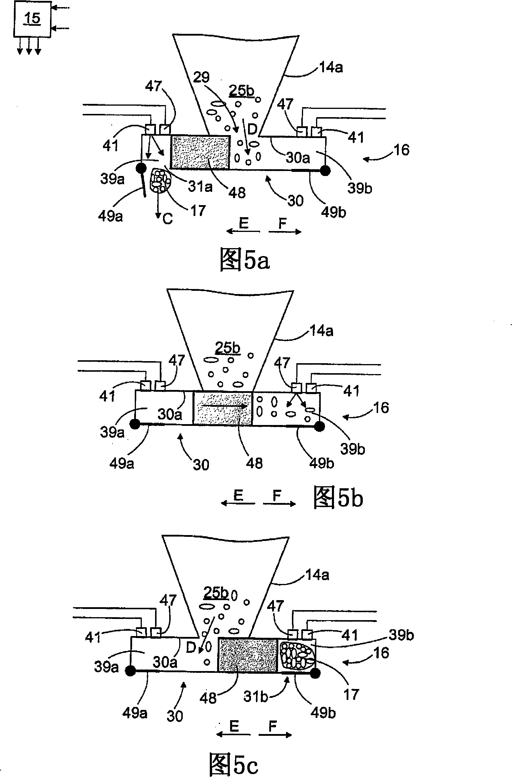
[0033] The rock drilling rig 1 shown in FIG. 1 includes a movable support 2 on which one or more movable drilling arms 3 may be arranged. The drilling boom 3 may have a drilling machine 4 comprising at least one feed beam 5 and a rock drill 6 . The rock drill 6 can move together with the feed beam 5 during drilling, while the percussion device belonging to the rock drill 6 supplies percussion pulses to the tool 7 . The drill bit 8 at the outermost end of the tool 7 then breaks the rock and the tool 7 penetrates the rock. During drilling, broken rock (i.e., drill cuttings) is produced and removed from the borehole 9 by supplying air, a mixture of air and water, or some other flushing medium through the tool 7 to the drill bit 8 from the flushing medium channel 10 these cuttings. The flushing medium pushes cuttings towards the borehole 9 which can be removed from the borehole by means of a collection system belonging to the drilling rig 1 .

[0034]The collection system compr...


PUM


Abstract

The invention relates to a method for processing dust when breaking rock, to a dust separator, and further to a rock-drilling rig. Rock material and air sucked from a borehole (9) or some other operating location is separated from each other in the dust separator (14). The separated rock material (25) falls into a discharge part (14a) of the dust separator, from which it can be dosed in batches into a discharging device (16). The discharging device comprises a closed compression space (39) in which the rock material batch is compressed into a more compact state. This forms a solid matter cake (17) that is removed from the dust separator (14).

Description

technical field [0001] The present invention relates to a method for handling dust when breaking rocks, the method comprising: sucking the crushed stone from the borehole and conveying it to a dust collector; separating the stone and air by the dust collector; metering the separated stones in batches from the dust collector; and removing the stones from the dust collector by means of a displacement feeder. [0002] The invention also relates to a dust remover comprising: a body, at least one suction device for generating a suction effect on the space formed by said body; at least one feed channel for supplying stone material to said dust remover and air; at least one separator for separating stone and air; at least one discharge channel along which air passing through said separator is removed from the dust collector; at least one discharge device for which Connected to the discharge section of the dust collector and arranged to remove separated stones from the dust collector...

Claims


Application Information

Patent Timeline
Patent Type & Authority Applications(China)
IPC IPC(8): B01D46/02B01D46/42E21B21/07B01D46/00B01D46/48B01D50/00B01FE21B21/015E21C
CPCB01D46/0068E21B21/07B01D46/48B01D50/002E21B21/015B01D46/71B01D50/20B01D46/02B01D46/42
Inventor 塔帕尼·索尔穆宁
Owner SANDVIK MINING & CONSTR OY
Learn More