Optical fiber connector

A technology of optical fiber splices and optical fibers, which is applied in the coupling of optical waveguides, etc., can solve the problems of difficult installation, many tools used, and complicated operation, and achieve the effects of low manufacturing cost, strong bonding, and not easy to break

Inactive Publication Date: 2008-12-03
JIANGSU UNIKIT OPTICAL TECH
View PDF0 Cites 2 Cited by
  • Summary
  • Abstract
  • Description
  • Claims
  • Application Information

AI Technical Summary

Problems solved by technology

[0002] At present, the installation of optical fiber cables for optical fiber connection sub-products mainly uses special tools to push the bare fiber by pressing the bent optical fiber sheath, so as to ensure the bonding of the optical fiber surface, and then rely on the single-point clamping device set in the sleeve Tight, the special tool cannot guarantee sufficient bonding force of the optical fiber, especially when the surface of the bare fiber is defective, it is even more difficult to ensure the true bonding of the fiber surface, and it cannot effectively prevent the rotation of the optical fiber cable. When an accidental force is applied during installation or use, it cannot Fully protect bare fiber
There is also a collet used for optical fiber connectors, which is provided with an equal-tapered helical surface on the surface of the locking head of the collet cylinder. Although this structure has reliable performance and automatic anti-rotation, but in the process of splicing, it is pressed tightly. When the device is pressed, a special tool must be used to push the sleeve. The operation is complicated, the tools used are many, and the continuous operation time is long, which brings many difficulties to the installation. Moreover, the structure of the chuck is complicated and difficult to manufacture.

Method used


Image

  • Optical fiber connector
  • Optical fiber connector
  • Optical fiber connector

Examples


Embodiment Construction

[0061] The present invention will be described in detail below in conjunction with the accompanying drawings.

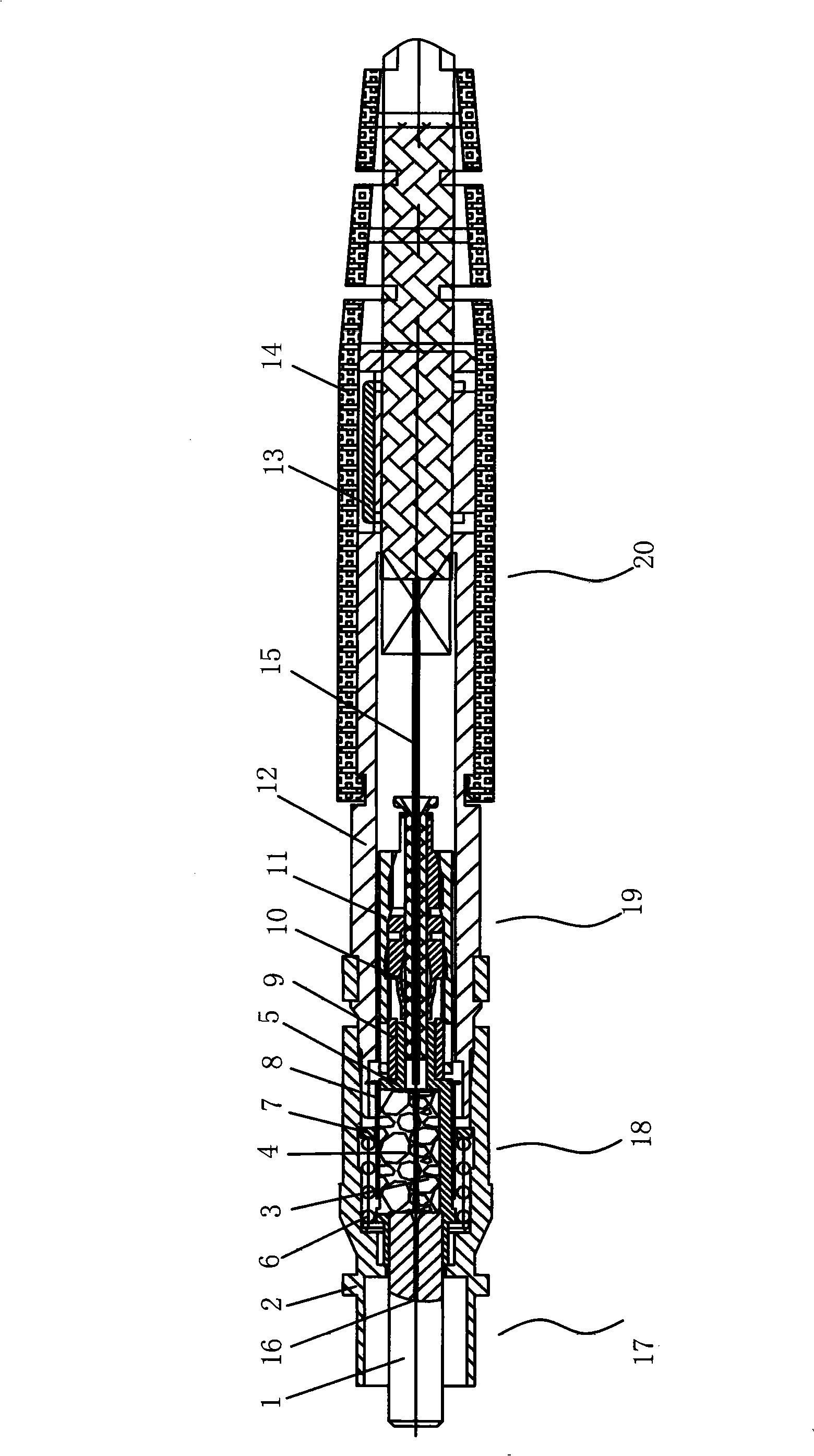
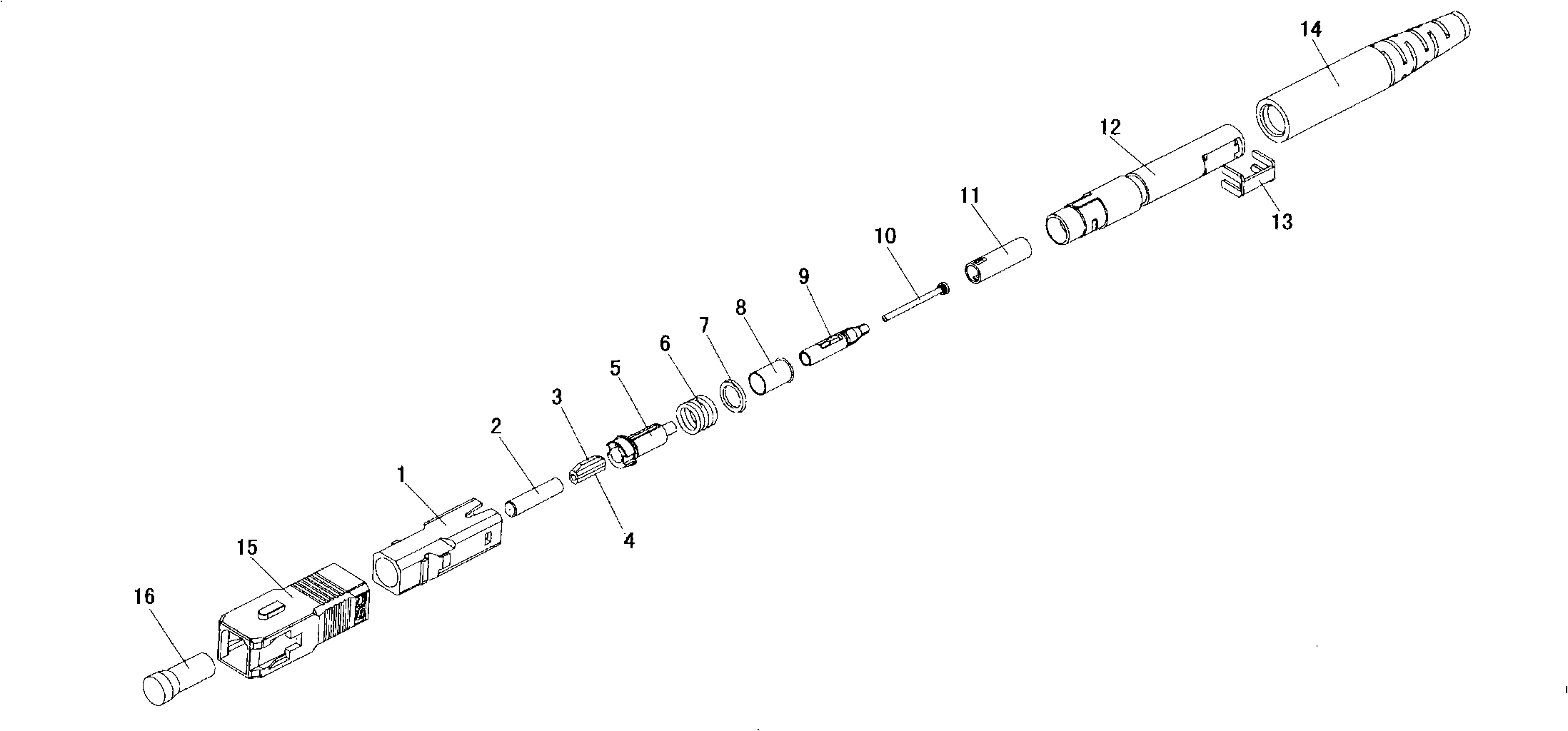
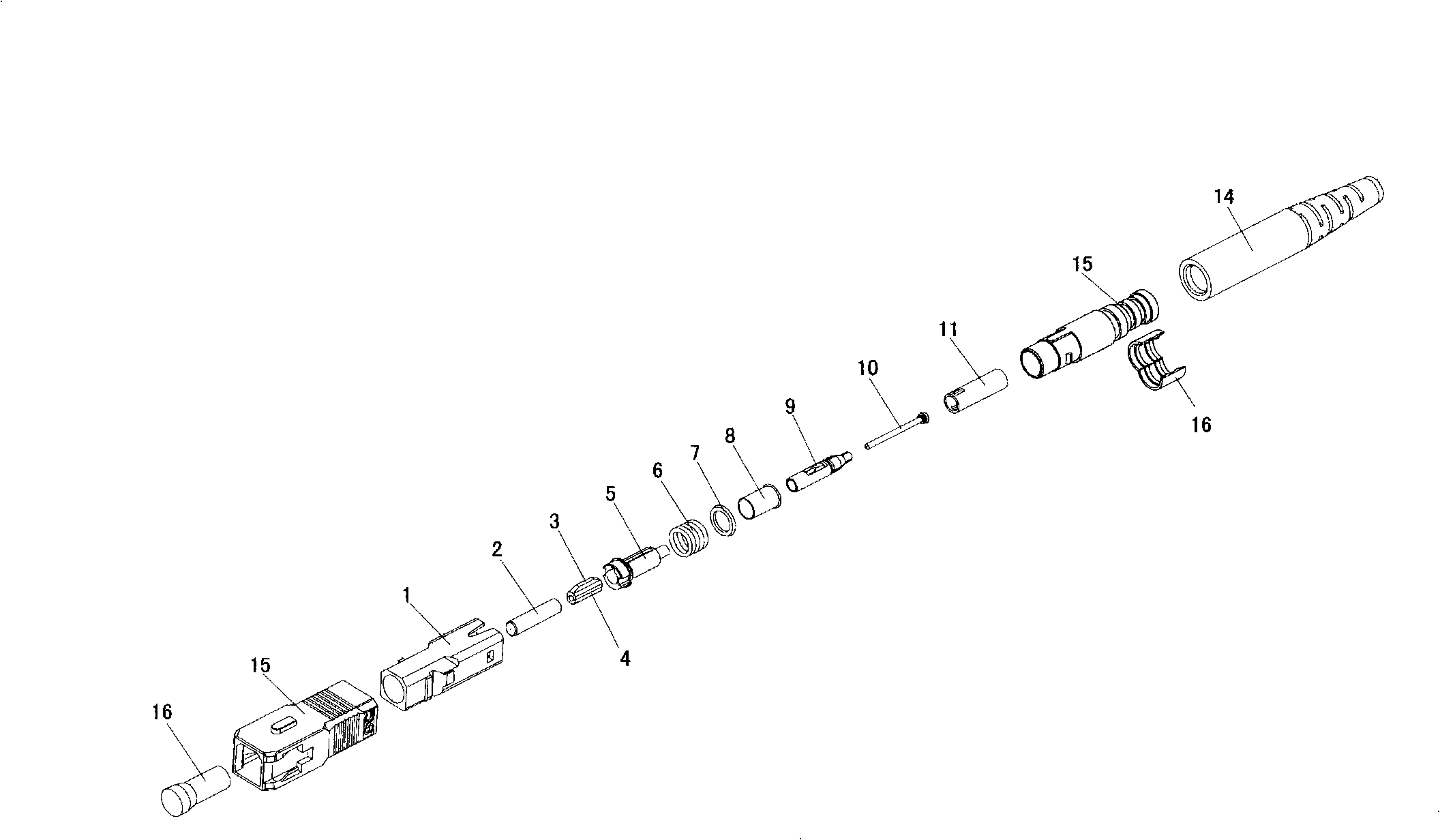
[0062] Such as figure 1 , 2 As shown, the optical fiber splice of the present invention includes a housing, and a guiding device 17 for guiding and positioning when the optical fiber is inserted, and a pressing device for compressing the bare fiber when the optical fiber is inserted in place are arranged in the housing. Tightening device 18 and locking device 19 for pushing and compressing the optical fiber; the tail of the housing is provided with the fastening device 20 for strongly clamping the outer skin of the optical fiber.

[0063] Such as Figure 5 , 8 and 9, the guide device 17 includes: the socket socket sleeve 5 and the pin 2. The pin holder sleeve 5 includes a through hole 5-1 for the front end to be mated with the pin 2 and a housing cavity 5-2 in the middle for accommodating the pressure block 3 and the gland 4. The pin 2 is crimped on the pin In th...


PUM


Abstract

The invention discloses a direct insert optical fiber splice, which comprises a casing, and a guiding device used for guiding and positioning, a pressing device used for pressing naked fiber, and a locking device which are arranged in the casing. The locking device comprises a cartridge and an ejection pipe; the cartridge comprises a cylindrical body with an optical fiber hole; at least two locking heads are arranged at one end of the cylindrical body; at least one pressing lug is arranged at the other end of the cylindrical body; an arc surface which can be stretched under pressure is arranged on the upper end surface of the pressing lug body, and is higher than the outer surface of the cylindrical body; and the ejection pipe is acted on the pressing lug to press and stretch the pressing lug. The quick splice of the invention has the advantages that no splicing point exists inside the splice, the optical fiber (APC) splicing with directional angle can be realized; the optical fiber can be automatically fitted; the fastening is reliable; and the control with super low insert loss can be realized, and is larger than the control of 60 return loss structure; the on-site polishing can also be performed; the return loss value during the optical fiber connection can be greatly reduced; and the overall production cost is low.

Description

technical field [0001] The invention relates to a connecting device used for installing optical fibers, which can ensure accurate positioning and orientation of optical fiber end faces during the splicing process. Background technique [0002] At present, the installation of optical fiber cables for optical fiber connection sub-products mainly uses special tools to push the bare fiber by pressing the bent optical fiber sheath, so as to ensure the bonding of the optical fiber surface, and then rely on the single-point clamping device set in the sleeve Tight, the special tool cannot guarantee sufficient bonding force of the optical fiber, especially when the surface of the bare fiber is defective, it is even more difficult to ensure the true bonding of the fiber surface, and it cannot effectively prevent the rotation of the optical fiber cable. When an accidental force is applied during installation or use, it cannot Fully protect bare fibers. There is also a collet used for ...

Claims


Application Information

Patent Timeline
Patent Type & Authority Applications(China)
IPC IPC(8): G02B6/38
Inventor 吕根良黄金安
Owner JIANGSU UNIKIT OPTICAL TECH
Why Eureka
Try Eureka