Large mode field optical fiber transmission system

A technology of optical fiber transmission and large mode field, which is applied in cladding optical fiber, bundled optical fiber, optical waveguide and optical guide, etc. It can solve the problems of unresolved optical fiber bending loss, inability to guarantee high-order modes, unfavorable manufacturing, etc., and achieve low connection loss and easy Fabrication, the effect of low bending loss

Active Publication Date: 2014-05-28
江苏大学扬州(江都)新能源汽车产业研究所
View PDF5 Cites 0 Cited by
  • Summary
  • Abstract
  • Description
  • Claims
  • Application Information

AI Technical Summary

Problems solved by technology

This method is not only difficult to operate, but also cannot guarantee that the high-order mode is completely and stably controlled between the two layers of air holes, and the fundamental mode will not lose at the same time.
The patent "A Large Mode Field Optical Fiber (200410011158.5)" discloses an optical fiber structure using an asymmetrical multi-clad annular core to achieve low-loss single-mode output of the optical fiber, but its structure is complex, which is not conducive to production, and it is not Solve the problem of bending loss of optical fiber

Method used


Image

  • Large mode field optical fiber transmission system
  • Large mode field optical fiber transmission system
  • Large mode field optical fiber transmission system

Examples


Embodiment 1

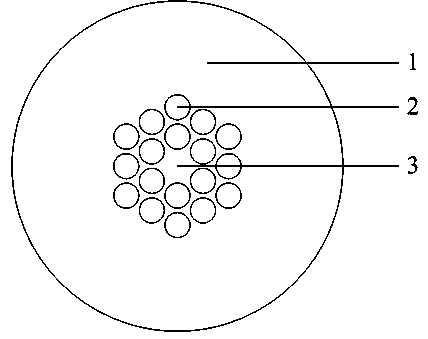
[0032] The cross-sectional structure of the main fiber is as figure 1 shown. The matrix material is pure silica, and the holes in the first auxiliary optical fiber, the second auxiliary optical fiber and the main optical fiber are filled with a solid material whose refractive index is lower than that of the matrix material. The length of the first auxiliary optical fiber at the input end is 10 mm, and the length of the second auxiliary optical fiber at the output end is 10 mm. The hole period Λ of the hole in the first auxiliary fiber 1 =38μm, hole diameter d 1 =15.2μm, the refractive index of the hole is 0.006 lower than that of the matrix material. The hole period in the main fiber is Λ=50μm, the hole diameter d=42.5μm, and the refractive index of the hole is 0.006 lower than that of the matrix material. The hole period Λ in the second auxiliary fiber 2 =33μm, hole diameter d 2 =13.2μm, the refractive index of the hole is 0.006 lower than that of the matrix material. ...

Embodiment 2

[0034] The cross-sectional structure of the main fiber is as figure 1 shown. The matrix material is pure silica, and the holes in the first auxiliary optical fiber, the second auxiliary optical fiber and the main optical fiber are filled with a solid material whose refractive index is lower than that of the matrix material. The length of the first auxiliary optical fiber at the input end is 10 mm, and the length of the second auxiliary optical fiber at the output end is 10 mm. Hole period Λ in the first auxiliary fiber 1 =54μm, hole diameter d 1 =21.6μm, the refractive index of the hole is 0.006 lower than that of the matrix material. The hole period in the main fiber is Λ=70μm, the hole diameter d=63μm, and the refractive index of the hole is 0.006 lower than that of the matrix material. Hole period Λ in the second auxiliary fiber 2 =45μm, hole diameter d 2 =18μm, the refractive index of the hole is 0.006 lower than that of the matrix material. The matrix material of t...


PUM


Abstract

The invention discloses a large mode field optical fiber transmission system which comprises a main body optical fiber, a first auxiliary optical fiber and a second auxiliary optical fiber, wherein the first auxiliary optical fiber and the second auxiliary optical fiber are connected to two ends of the main body optical fiber respectively. The main body optical fiber, the first auxiliary optical fiber and the second auxiliary optical fiber are photonic crystal fibers. Covering layers of the three optical fibers are composed of hose materials (1) and holes (2) distributed on a regular grid, and a fiber core (3) is formed by a hole lost in the regular grid. Solid materials with the refraction rate lower than that of the hose materials are filled in the holes (2). The main body optical fiber is a multimode optical fiber, and the first auxiliary optical fiber and the second auxiliary optical fiber are single mode fibers. Through the large mode field optical fiber transmission system, the aim of large mode field, low connection loss and low bending loss single mode transmission is achieved.

Description

technical field [0001] The invention relates to the field of optical fiber communication, in particular to a novel structured optical fiber for transmission with large mode field, low connection loss and low bending loss. Background technique [0002] In the application and development of high-power fiber lasers and amplifiers, nonlinear effects and fiber damage have become important factors that restrict the power increase, and the single-mode transmission of large-mode-field fibers can effectively overcome these unfavorable factors. Therefore, the main fiber technology is now One of the development trends is optical fibers capable of large mode field single-mode transmission for various applications. In traditional methods, step-index fibers are often used to realize large-mode-field single-mode fibers, but their minimum bending radius is relatively large, and a small amount of high-order modes still exist in them. At the same time, in order to maintain the single-mode t...

Claims


Application Information

Patent Timeline
Patent Type & Authority Patents(China)
IPC IPC(8): G02B6/02G02B6/04
Inventor 陈明阳张银许孝芳
Owner 江苏大学扬州(江都)新能源汽车产业研究所
Why Eureka
Try Eureka