Eureka AIR delivers breakthrough ideas for toughest innovation challenges, trusted by R&D personnel around the world.

Connecting structure for suspendome

A technique for a chord-supported dome and a connecting structure, which is applied in the field of construction, can solve the problems of large deviation between the measured value of prestress and the design value, increase the index of steel used, and less engineering application, so as to ensure the construction quality, eliminate the processing error, and facilitate the construction site. The effect of installation

Inactive Publication Date: 2008-12-03
ZHEJIANG UNIV
View PDF0 Cites 17 Cited by
  • Summary
  • Abstract
  • Description
  • Claims
  • Application Information

AI Technical Summary

Problems solved by technology

[0004] 1) In the structure, the vertical struts, oblique cables and ring cables intersect at one point, and the design of this node has not yet formed a mature theoretical system
[0005] 2) Although a variety of prestressed construction methods have been proposed for the suspensed dome structure, there are few practical engineering applications, and there are still too many prestressed losses, large deviations between the measured prestressed value and the designed value, and cannot be adjusted
[0006] 3) Due to the limitation of the current design nodes, it is very difficult to adjust the applied prestress, which makes it unnecessary to consider this problem in the design of the actual suspension dome structure, thus increasing the steel index, and some suspension domes Structural cables become decoration

Method used


Image

  • Connecting structure for suspendome
  • Connecting structure for suspendome
  • Connecting structure for suspendome

Examples


Embodiment Construction

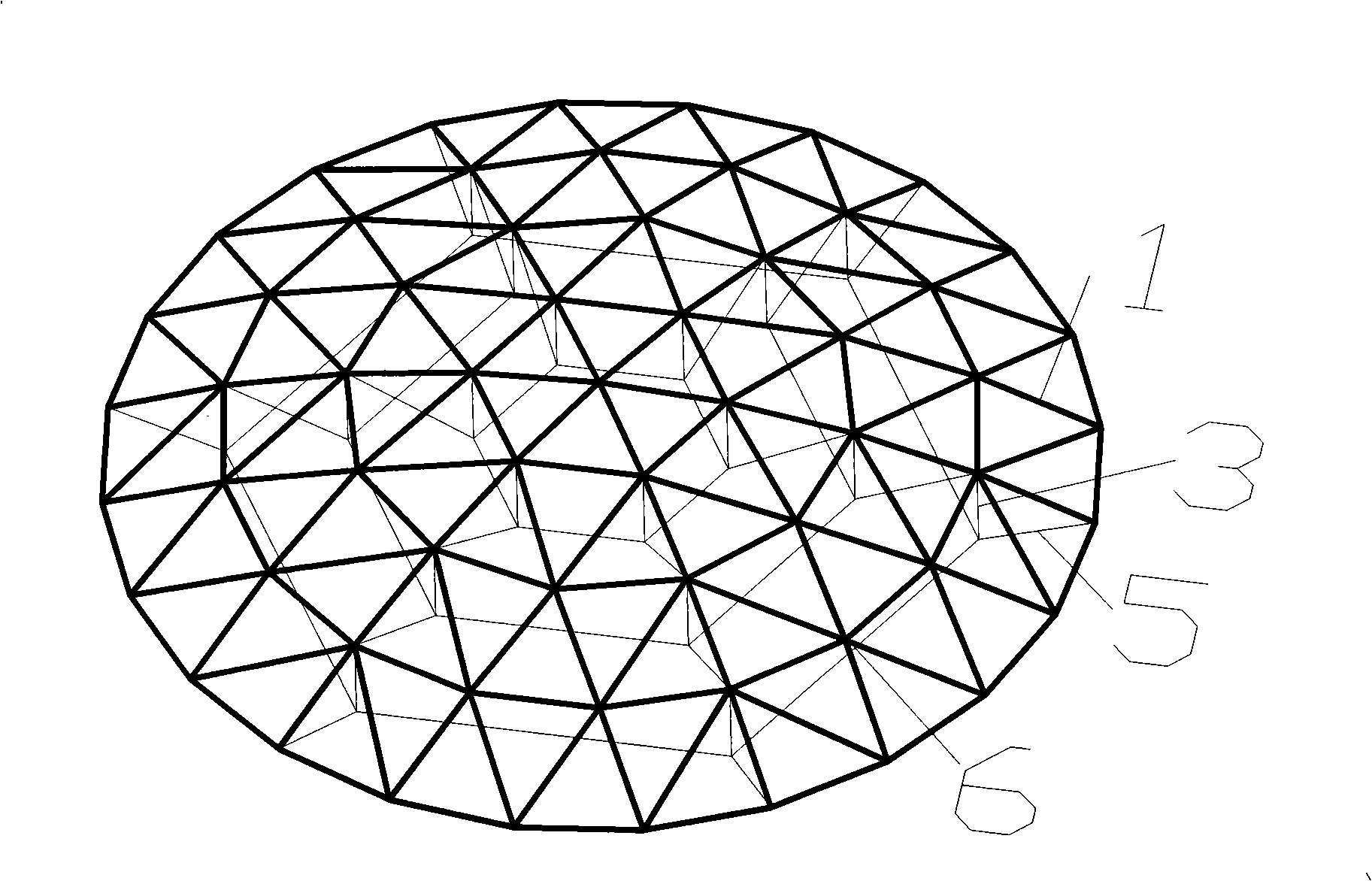
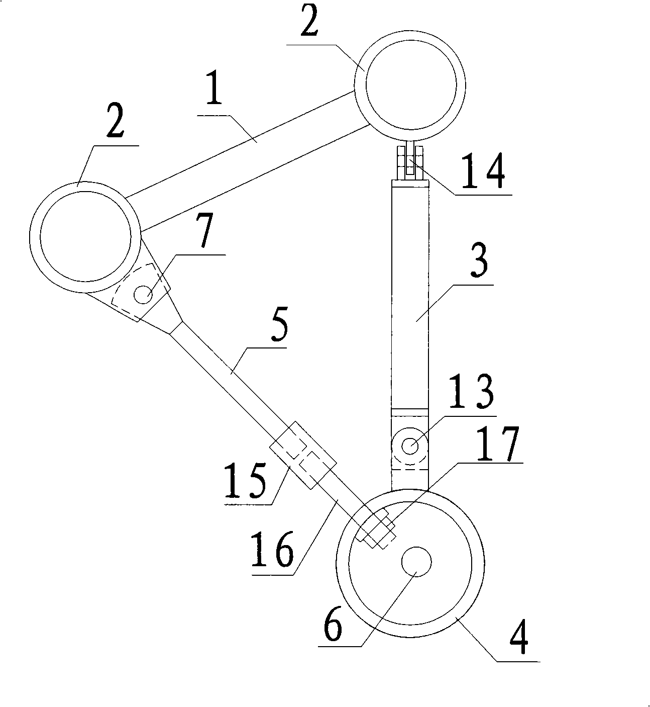
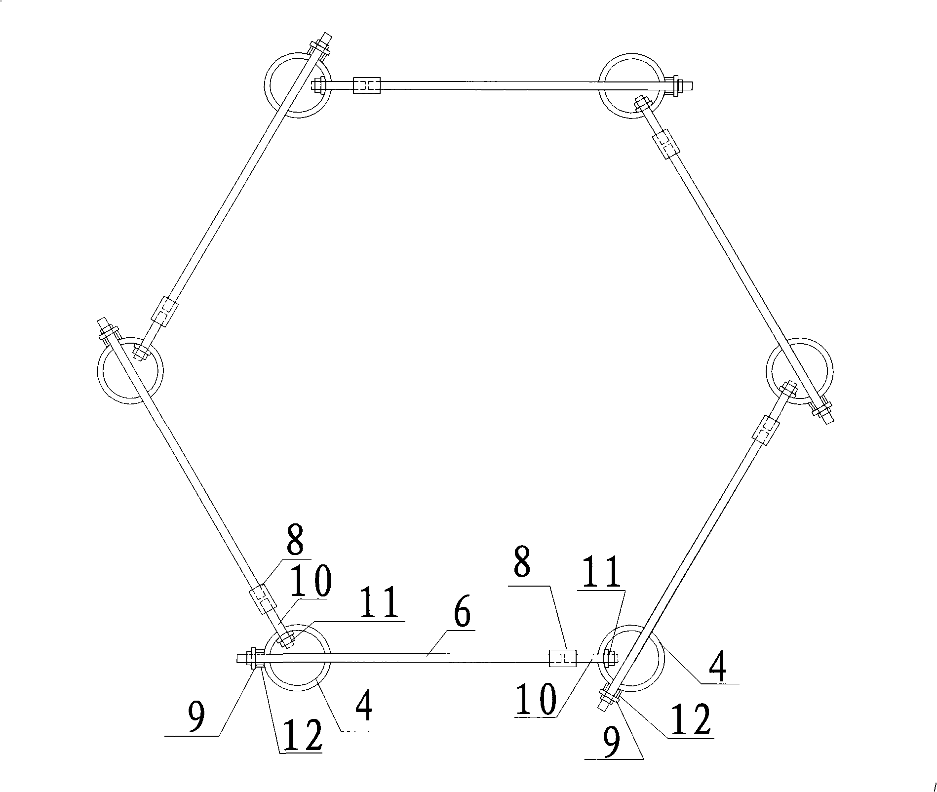
[0021] The connection structure for the suspendome structure includes upper chord reticulated shell rods 1, upper chord reticulated shell nodes 2, vertical compression bars 3, welded hollow spherical nodes 4, oblique cables 5, ring cables 6, first pin bolt connection joints 7, First threaded sleeve 8, first nut and backing plate 9, first cable head 10, second nut and backing plate 11, support pipe 12, second pin connection joint 13, third pin connection joint 14 , the second threaded sleeve 15, the second cable head 16, the third nut and the backing plate 17; the rod 1 and the node 2 form the reticulated shell structure part of the suspensive dome structure, the oblique cable 5, the ring cable 6 and the vertical pressure Rods 3 are connected by welded hollow ball joints 4; welded ball joints 4 have three holes in the direction of the horizontal hoops, two of which allow a hoop 6 to pass through the welded ball joints 4 and pass through the first nut and backing plate 9 Anchori...


PUM


Abstract

The invention discloses a connecting structure used for a suspend-dome structure. The suspend-dome structure is a structure formed by connecting an upper chord single-layer spherical reticulated shell, an oblique cable and hoop cables through a vertical compression rod. In the connecting structure, the oblique cable, the hoop cables and the vertical compression rod are connected with each other through a welded hollow spherical joint. The welded hollow spherical joint forms three holes in the horizontal hoop cable direction, wherein two holes allow one hoop cable to penetrate the welded hollow spherical joint and be anchored through a cast anchor, the other hole allows a washer inside the welded hollow spherical joint to be anchored with a screw cap to form a connecting cable head, and the connecting cable head is connected with a threaded sleeve through the other hoop cable; the welded hollow spherical joint forms the other hole in the oblique cable direction, the washer used inside the welded hollow spherical joint is anchored with the screw cap to form the other connecting cable head, and the connecting cable head is connected with the hoop cables through the threaded sleeve. After the connecting structure is adopted, the construction of the suspend-dome structure is very convenient, the cable force can be adjusted times and again, and the disadvantage that the cable force in the prior suspend-dome structure engineering is difficult to be consistent with the theoretical value can be overcome.

Description

technical field [0001] The invention relates to the field of architecture, in particular to a connection structure for a suspend dome structure. Background technique [0002] Suspension dome structure is a new structural form proposed by Japanese scholar M Kawaguchi in 1993. It combines the advantages of single-layer reticulated shell and cable dome structure, and has good mechanical properties. The suspensive dome structure is a self-balancing structural system based on improving the stability of the single-layer spherical reticulated shell and reducing the dependence on external components. On the one hand, it improves the stability of the single-layer reticulated shell structure and enables the structure to span larger space; on the other hand, the new structural system is a self-balancing system, which does not need to be shaped by external components, reducing the dependence on external components. [0003] But it also has the following problems: [0004] 1) In the s...

Claims


Application Information

Patent Timeline
Patent Type & Authority Applications(China)
IPC IPC(8): E04B7/08E04B7/14E04B1/32E04B1/342
Inventor 高博青张瑞汪毅俊陈春雷
Owner ZHEJIANG UNIV
Why Eureka
Eureka Blog
Learn More