Shielding surface apparatus with space capable of being expanded
A shielding surface and space technology, which is applied in the aerospace field, can solve the problems of structural surface density, configuration accuracy, and the storage rate cannot reach the use target, and achieve the effect of excellent storage rate, simple form and light weight.
- Summary
- Abstract
- Description
- Claims
- Application Information
AI Technical Summary
Problems solved by technology
Method used
Image
Examples
example 1
[0062] Example 1, a circular space with a diameter of 3m is deployed to place a planar support device.
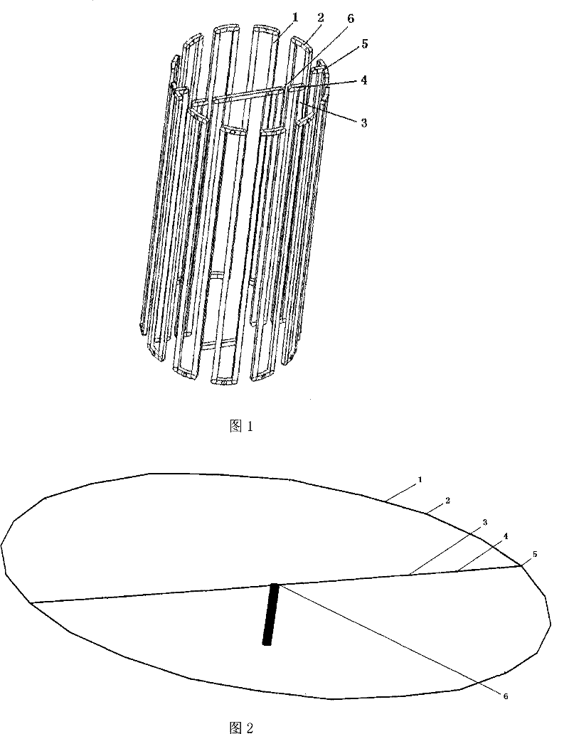
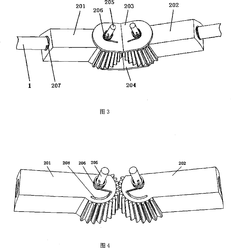
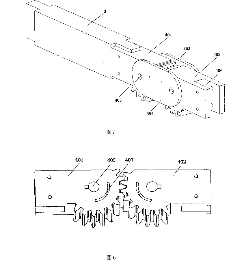
[0063] The collapsed state of the device is as figure 1 As shown, the expanded state is as figure 2 shown. There are 24 ring rods on the caliber ring structure, and a total of 8 rib rods on the two radial supporting rib structures. Both the ring bar and the rib bar are straight bars with a rectangular solid section of 0.006m×0.004m. The ring rod connection joint adopts image 3 The two conical synchronous gear mechanisms driven by the torsion spring shown in , the connection angle of the two synchronous mechanisms is 165 degrees. The rib-rod connection joint adopts Figure 5 Two cylindrical synchronous gear mechanisms driven by torsion springs shown in . The ring bar and the rib bar adopt the Figure 5 The groove structure shown in the figure is respectively assembled with the ring-rod connecting joint and the rib-rod connecting joint. ring structure and rib struct...
example 2
[0066] Example 2, a square space offset planar support device with a diameter of 8 m is deployed.
[0067] The collapsed state of the device is as Figure 9 shown. There are 4 ring rods on the caliber ring structure, and a straight rod with a rectangular solid section of 0.010m×0.008m is used. The ring rod adopts the Figure 5 The groove structure shown in the figure is assembled with the connecting joint of the ring rod to form an overall rigid structure that can be folded and unfolded. The ring rod connection joint adopts image 3 The two conical synchronous gear mechanisms driven by the torsion spring shown in , the connection angle of the two synchronous mechanisms is 90 degrees. ring structure through Figure 10 The installation holes 708 shown in the middle and outer connection joints 7 are assembled with the corresponding structures of the spacecraft. The entire structure of the device is made of aluminum alloy, which is packed into a cuboid of about 0.15m×0.15m×5...
example 3
[0069] Example 3, deploying a circular upright plane support device with a diameter of 20m, applied to the ground environment.
[0070] The unfolded state of the device is as Figure 11 shown. There are 36 ring rods on the caliber ring structure, which are straight rods with an outer diameter of Ф0.026m and an inner diameter of Ф0.020m; the central cylinder 8 adopts a round pipe with an outer diameter of Ф0.20m, an inner diameter of Ф0.18m and a height of 10m As a pillar, it is consolidated on the ground; the ring rod connection joint 2 adopts image 3 Shown structure, and can offer a hole on the outer splint 204 of this ring bar connection joint, be used for wearing flexible rope 9. The ring rod adopts the image 3 The threaded hole structure shown in is assembled with the ring-rod connection joint, and the connection angle of the two conical synchronous gear mechanisms is 170 degrees. The entire structure of the device is made of aluminum alloy, and it is packed in a cyl...
PUM
 Abstract
Description
Claims
Application Information
 - Generate Ideas
- Intellectual Property
- Life Sciences
- Materials
- Tech Scout
- Unparalleled Data Quality
- Higher Quality Content
- 60% Fewer Hallucinations
Browse by: Latest US Patents, China's latest patents, Technical Efficacy Thesaurus, Application Domain, Technology Topic, Popular Technical Reports.
© 2025 PatSnap. All rights reserved.Legal|Privacy policy|Modern Slavery Act Transparency Statement|Sitemap|About US| Contact US: help@patsnap.com


