Moving object detecting apparatus and method using light track analysis

A technology for moving objects and detection devices, applied in image analysis, image data processing, instruments, etc., can solve the problems of difficulty in obtaining depth information and slow calculation speed in smooth images

Active Publication Date: 2008-11-26
IND TECH RES INST
View PDF4 Cites 12 Cited by
  • Summary
  • Abstract
  • Description
  • Claims
  • Application Information

AI Technical Summary

Problems solved by technology

However, the calculation speed is slow, and multiple cameras are required to obtain the d

Method used


Image

  • Moving object detecting apparatus and method using light track analysis
  • Moving object detecting apparatus and method using light track analysis
  • Moving object detecting apparatus and method using light track analysis

Examples


Embodiment Construction

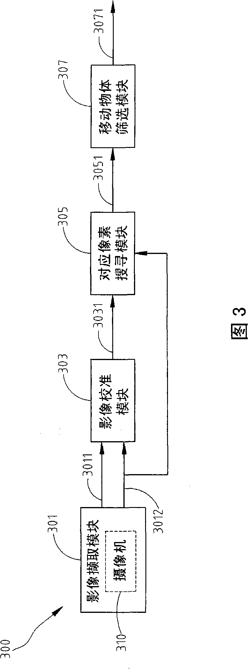
[0063] FIG. 3 is a schematic diagram of an example of a mobile object detection device using light trace analysis of the present invention. Referring to FIG. 3 , the moving object detection device 300 using light trace analysis includes an image capture module 301 , an image calibration module 303 , a corresponding pixel search module 305 and a moving object screening module 307 .

[0064] The image capture module 301 continuously captures multiple images, for example, captures multiple images from a surveillance scene when a camera 310 is moving or still. The image capture module 301 serves as an input component of the moving object detection device 300 using light trace analysis. The image calibration module 303 obtains a calibrated front image 3031 from every two input adjacent images, called the front image 3011 and the back image 3012 . After the image calibration is completed, the corresponding pixel search module 305 finds the optical trajectory displacement of each pi...


PUM


Abstract

The invention relates to a movable object detection device adopting light tail analysis and a method thereof. The device comprises four modules as an image picking, an image calibration, pixel searching and movable object selection modules. The invention can continuously pick up images when the background of the camera is movable and stable, according to the input adjacent images, estimate the image correlation of the adjacent images, estimate a calibration conversion parameter of the adjacent images and according to the calibration conversion parameter, calibrate the background area of the adjacent images to calculate a calibrated front image. After the calibration, the invention tracks the displacement vector of corresponding pixels of each pixel in the adjacent images and combines the information generated by light tail track, to stably and correctly judge the position of the movable object in the image. The invention is not interfered by noise error and can be applied for detecting the movable object of a movable or fixed camera platform.

Description

technical field [0001] The invention relates to a moving object detection device and method using optical flow analysis. Background technique [0002] Moving object detection plays a very important role in automated surveillance (surveillance) systems. The video surveillance system can detect the occurrence of abnormal security incidents by analyzing the trajectory and behavior of moving objects in the surveillance screen, and effectively notify security personnel to deal with them. [0003] However, most of the traditional monitoring environments set up multiple fixed cameras for monitoring in the monitoring scene, which cannot provide dynamic security support when abnormal events occur. Therefore, the concept of using mobile cameras is gradually emerging. However, under the mobile camera monitoring framework, the movement of the camera may cause the overall picture to change, making it impossible to directly apply traditional image-based moving object detection technology...

Claims


Application Information

Patent Timeline
IPC IPC(8): H04N7/18G06T7/20
Inventor 富博超石明于
Owner IND TECH RES INST
Why Eureka
Try Eureka