
Control method and apparatus for mechanical absolute zero position in stepper motor transmission system

A stepping motor and transmission system technology, applied in the direction of motor generator control, feedback control, control system, etc., can solve the problems of stepping motor out of step, inaccurate positioning, increased circuit cost, etc., so as to facilitate popularization and application , Reliable method and simple device

Inactive Publication Date: 2008-11-12
JIANGSU UNIV
View PDF1 Cites 7 Cited by
  • Summary
  • Abstract
  • Description
  • Claims
  • Application Information

AI Technical Summary

Problems solved by technology

However, in actual use of this method, due to the rigid contact between the end of the moving machine and the dead stop, the stepping motor is out of step, making it difficult for the end of the moving machine and the dead stop to really stick together tightly, resulting in an absolute Zero positioning is not accurate
[0005] Prior art Chinese patent 200410018182.1 etc. discloses a control method for the absolute zero position of a stepping motor, but there are the following problems: (1) a positioning sensor device is arranged on the rotor shaft of the stepping motor, as a precise judgment signal of the moving machinery in place , the sensor signal needs to be adjusted again, which increases the circuit cost; (2) After the controller receives the fine judgment signal, the controller immediately sends a stop signal to stop the transmission system, but due to the mechanical inertia, the transmission system cannot stop immediately , resulting in inaccurate positioning; and the transmission system is in rigid contact, which will cause the stepping motor to lose step (3) In practical applications, the installation of the sensor device is inconvenient

Method used


Image

  • Control method and apparatus for mechanical absolute zero position in stepper motor transmission system

Examples


Embodiment Construction

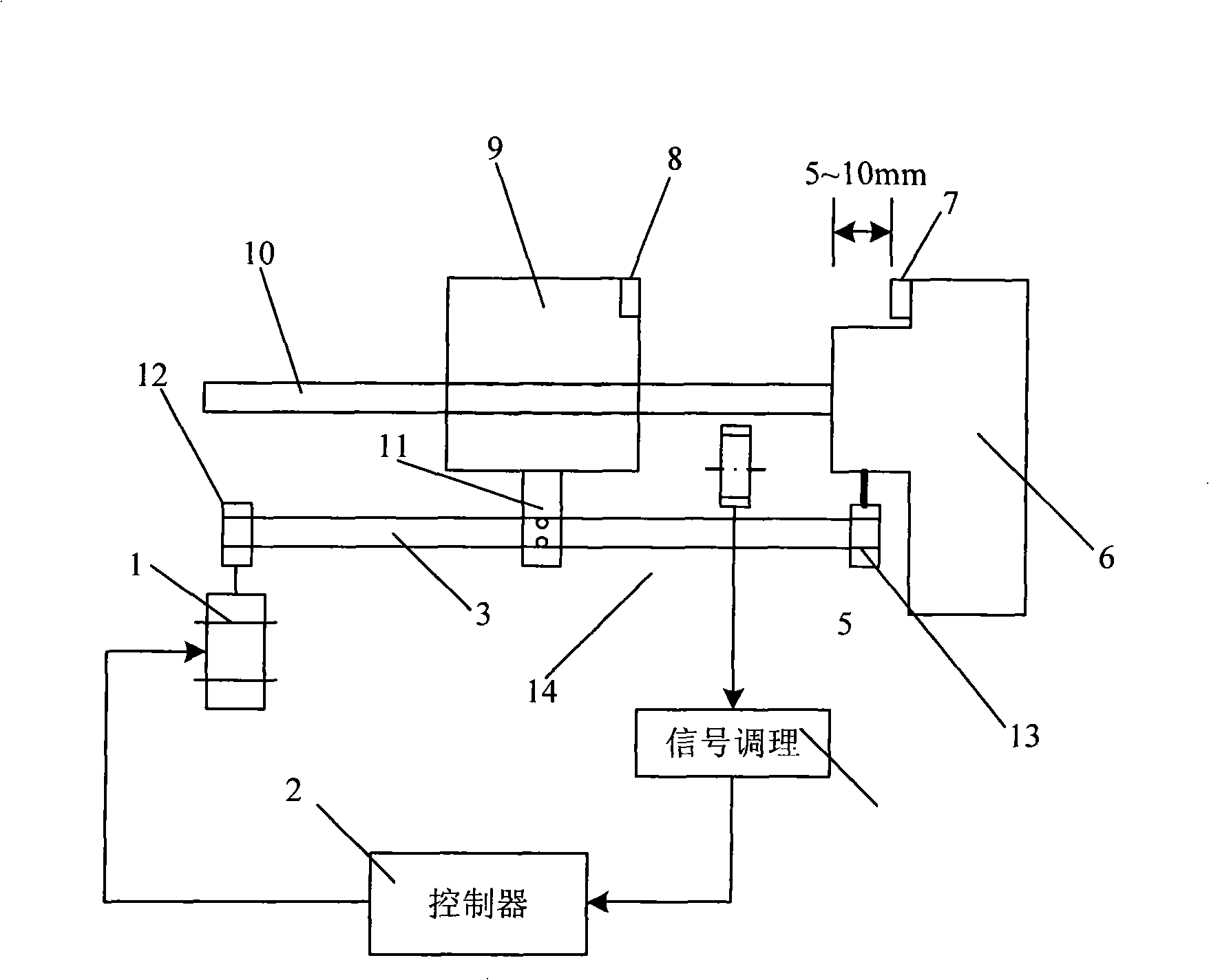
[0012] figure 1 A transmission system structure driven by a stepping motor is given, including a transmission device 14 driven by a stepping motor 1, which is composed of a synchronous belt 3 connected to the stepping motor 1 and a movable belt fixedly connected by a pressure block 11. 9 composition of sports machinery. The stepping motor 1 drives the moving machine 9 to move along the guide rail 10 through the timing belt 3 and the pressure block 11 on it, so that the rotary motion of the stepping motor is converted into a linear motion, wherein the timing belt 3 is fixed by the fixed pulleys 12 and 13 on the mechanical device. The end position of the transmission device 14 is provided with an in-position sensor 5 (such as a photoelectric switch or a travel switch, etc.). After the signal conditioning 4, the in-position sensor 5 is shaped into a standard TTL signal and connected to the controller 2. After the in-place signal (coarse judgment signal) of part 9, power-off is ...


PUM


Abstract

A mechanical absolute zero position controlling method in a stepping motor driving system adopts a two-step positioning method. The method is as follows: firstly, an in place sensor is used for receiving an in place signal of the distance between a moving machine moving to a baffle block and the preset gap; the signal is transformed and conditioned and then is transmitted to a controller; the controller switches off electricity to a stepping motor as soon as receiving the signal, which is a coarse positioning; then, the heteropolar magnets which are arranged face to face at the corresponding position of the end of the moving machine and the stepping motor are pulled in each other to achieve a precise position, that is an absolute zero position. The mechanical absolute zero position controlling method in the stepping motor driving system designed by the method is provided with the stepping motor controlled by a controller; the stepping motor drives the moving machine to move along a guide rail to the baffle block in a straight line. The end of the moving machine is provided with an in place sensor, an in place sensor output connected with the controller by a adjusting and shaping circuit. Two heteropolar magnets are arranged face to face on the corresponding position of the end of the moving machine and a dead baffle block respectively.

Description

technical field [0001] The present invention relates to the control of mechanical absolute zero position in transmission system, in particular to a control method of mechanical absolute zero position in a stepping motor transmission system in which a stepping motor is used as a power source and the stepping motor drives mechanical parts to perform frequent reciprocating motions and its device. Background technique [0002] Most transmission systems, such as CNC machine tools, nucleic acid extractors, automatic biochemical analyzers, etc., require their moving machinery to make frequent reciprocating movements to complete the actions specified in the process. This type of instrument generally uses a stepping motor as a power source. The main reason is that the stepping motor is a motor that converts pulse signals into angular displacements, and its angular displacements strictly correspond to the number of input pulses. Therefore, the control is relatively simple and easy to...

Claims


Application Information

Patent Timeline
IPC IPC(8): H02P8/30G05D3/12
Inventor 潘天红盛占石营胜
Owner JIANGSU UNIV
Learn More