
Solar strong effect extension concentration apparatus

A concentrating device and solar energy technology, which is applied in the direction of solar thermal devices, solar thermal energy, solar thermal power generation, etc., can solve the problems of high price, high price of solar silicon chips, and less thermal power, and achieve the effect of increasing power generation

Inactive Publication Date: 2008-11-12
林于纮
View PDF0 Cites 15 Cited by
  • Summary
  • Abstract
  • Description
  • Claims
  • Application Information

AI Technical Summary

Problems solved by technology

[0002] Commonly used solar concentrating devices on the market are shown in Fig. 31: a solar concentrating device, a group of solar energy collectors directly facing the sunlight 52, and after the solar silicon chips 42 are connected in series and parallel, a group of storage batteries 54 are connected, and the solar silicon chips 42 are connected to each other. The generated electric energy is stored in the battery 54 or directly supplied to electrical appliances. According to expert research, the application of solar silicon chips to solar energy collectors is really overkill. Solar silicon chips can withstand several times the sunlight and can emit several times Moreover, the production technology of solar silicon chips is controlled by foreign manufacturers, the price of solar silicon chips remains high, and the thermal power generated by solar energy collectors is so little that the benefit rate of installing solar energy collectors cannot be improved. Everyone knows that Solar energy is green energy, which is inexhaustible and inexhaustible. It is an inexhaustible green energy that does not require money to buy. However, the electric energy or heat collected by the solar energy collector is small and the device is expensive. Therefore, solar energy concentrators have not been able to be effectively promoted, and everyone knows that convex lenses can concentrate light, but why no manufacturer has applied convex lens concentrators to solar energy concentrators, so there is a lot of room for improvement in conventional solar energy concentrators

Method used


Image

  • Solar strong effect extension concentration apparatus
  • Solar strong effect extension concentration apparatus
  • Solar strong effect extension concentration apparatus

Examples


Embodiment Construction

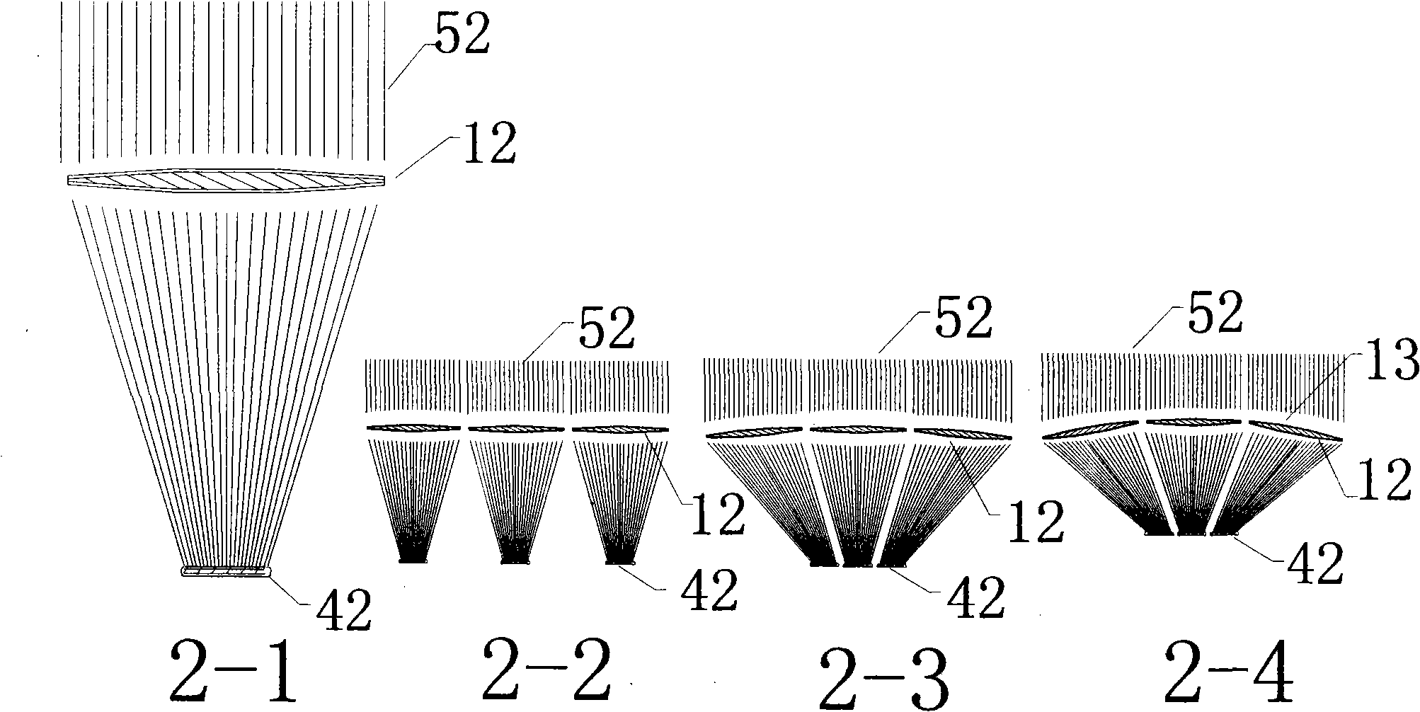
[0042] 1. The description of the light concentrating device in this case is shown in Figure 2: a schematic diagram of the light concentrating by the convex lens. As shown in Figure 2-1, a large-area convex lens 12 is very heavy, and the focal length of the large-area convex lens is very long. The large-area convex lens is not easy to manufacture and is expensive. Using a large-area convex lens as a solar concentrating device is bulky. The weight is very heavy and the price is expensive. As shown in Figure 2-2, the large-area convex lens is changed to a small convex lens 12. The small convex lens is easy to manufacture and the price is low. The focal length is short. The volume of the light-collecting device can be reduced, so several small convex lenses Arranged on a plane, several small convex lenses arranged on the plane is a plane compound eye condenser.

[0043] As shown in Figure 2-3, when several small convex lenses are arranged on a plane, the focal points of the small ...


PUM


Abstract

The invention discloses a powerful solar energy extending photospot device; a shell is internally provided with a group of solar energy collecting devices and an extension condenser lens. The upper part of the solar energy integrator is provided with an extension condenser lens which is fixedly arranged on an adjustable frame; the adjustable frame can adjust the extension condenser lens towards the solar source; the extension condenser lens can integrate solar energy into the solar energy collecting devices and can effectively shorten the distance between the condenser and the solar energy collecting devices to lead a solar energy generator or a collector to emit times of electric energy and heat energy.

Description

Technical field [0001] The invention relates to a solar concentrating device, in particular to a powerful extended solar concentrating device with an extended concentrator and an adjustable bracket. The extended concentrator can gather several times the solar energy, and the adjustable bracket can adjust the direction of the extended concentrator. The solar light source concentrates the sunlight on the solar energy collector, and the extended condenser effectively shortens the distance between the condenser and the solar energy collector, and gathers several times the sunlight energy on the solar energy collector, so that the solar generator or heat collector Send out several times the electric energy or heat energy. Background technique [0002] Commonly used solar concentrating devices on the market are shown in Fig. 31: a solar concentrating device, a group of solar energy collectors directly facing the sunlight 52, and after the solar silicon chips 42 are connected in se...

Claims


Application Information

Patent Timeline
Patent Type & Authority Applications(China)
IPC IPC(8): H02N6/00G02B3/00G02B7/04G05D3/00F24J2/06F24J2/38F24S23/00F24S50/20H02S20/32H02S40/22
CPCY02E10/47Y02E10/44Y02E10/50
Inventor 林于纮
Owner 林于纮
Learn More