Optical elements for high contrast applications

A technology of optical components and multi-layer optical films, which can be used in optical components, optics, instruments, etc., and can solve problems such as poor performance of front projection screens

Inactive Publication Date: 2008-11-05
3M INNOVATIVE PROPERTIES CO
View PDF24 Cites 18 Cited by
  • Summary
  • Abstract
  • Description
  • Claims
  • Application Information

AI Technical Summary

Problems solved by technology

Existing front projection screens perform poorly in high ambient light conditions

Method used


Image

  • Optical elements for high contrast applications
  • Optical elements for high contrast applications
  • Optical elements for high contrast applications

Examples


example 1

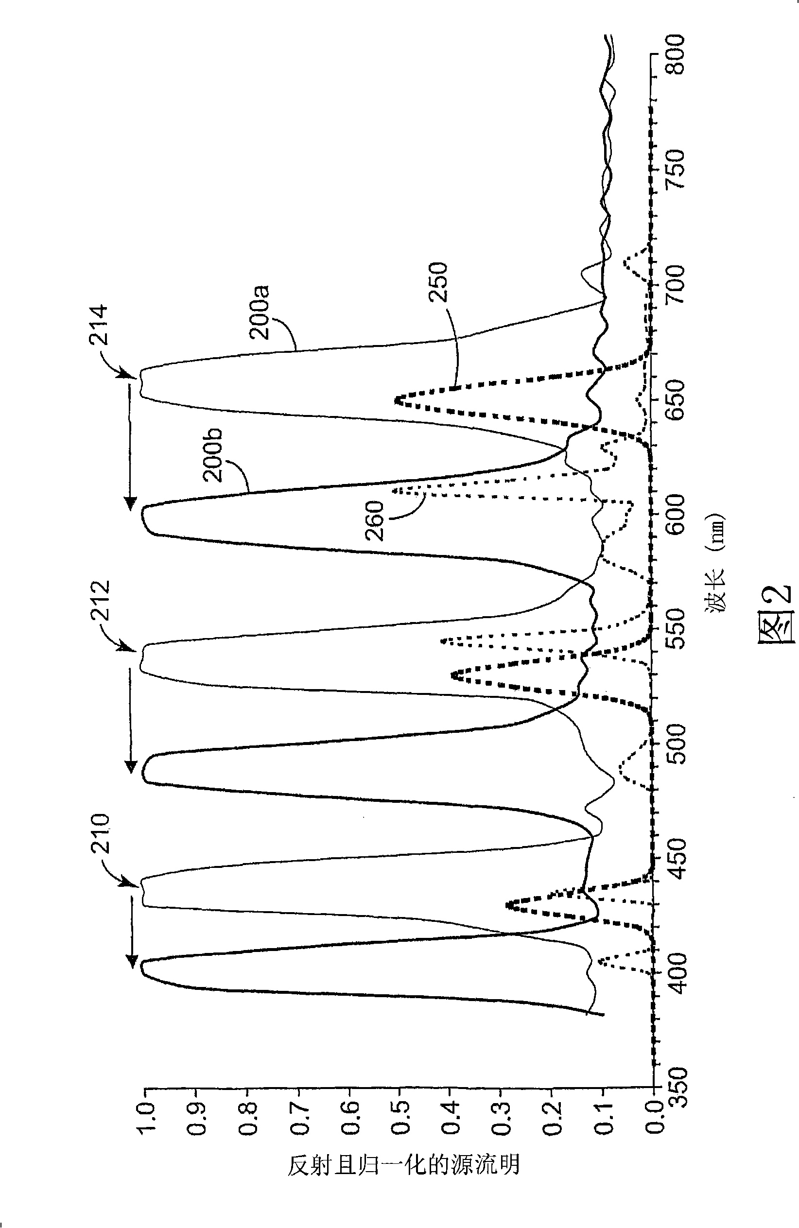
[0077] In Example 1, the computational construction (ie, model design) included the optical elements of a multilayer optical film mirror. The MOF structure consists of 3 quarter-wavelength stacks of coherent multilayer optical films, each stack including 160 layers of polycarbonate (material 1) and PMMA (material 2). All materials in Example 1 are isotropic, and their refractive index n 1 = 1.579, and n 2 = 1.495. The lower index PMMA layer is at the air to interference stack reflector interface. These settings reduce the degree of reflection in the wavelength region between the reflection bands of the interference stack. Each set of coherent stacks of alternating polymer microlayers (herein referred to as "blue light reflective interference stacks", "green light reflective interference stacks", etc.), is designed to have a reflection band around a designed visible wavelength. Equation 1 represents the center wavelength λ of the first-order harmonic (m=1) reflection band ...

example 2

[0090] In Example 2, a MOF reflective polarizer was computationally constructed. The MOF structure consists of three coherent multilayer quarter-wavelength stacks, each containing 160 birefringent polyethylene naphthalate (PEN; material 1) and non-birefringent copolymer microspheres of PEN. layer (co-PEN; material 2), the refractive index n of the polyethylene naphthalate microlayer in the stretching direction 1,stretch =1.757, the refractive index n in the harmonic direction 1,match = 1.614, the refractive index n of its non-birefringent copolymer 2 = 1.612. The lower index co-PEN layer is assumed to be at the air-to-interference stack interface. This reduces the degree of reflection in the wavelength region between the reflection bands of the interference stack. As in the case of Example 1 with MOF mirrors, each coherent interference stack is designed to have a reflection band at a designed visible wavelength to harmonize the light output spectrum of the projector. Equa...


PUM


Abstract

The present application discloses optical elements for use in applications where high contrast is desirable. The optical elements comprise a multilayer optical film having a plurality of reflection bands at design wavelengths of incident light, wherein at least one of the reflection bands is a narrow reflection band, wherein each reflection band has a nominal spectral position at a design angle of incidence and wherein each reflection band shifts to a color-shifted reflection band for light incident at angles other than the design angles. The optical elements also comprise a wavelength selective absorber for absorbing at least one of the color-shifted reflection bands.

Description

technical field [0001] The present patent application relates to optical elements used as reflective elements in high-contrast applications. Background technique [0002] As we all know, there are many kinds of front projection screens. Existing front projection screens do not perform well in high ambient light conditions. For example, in a typical conference room, use of a projection system requires the user to reduce the ambient light intensity in the room in order to view the projected image on the screen. Reducing the indoor ambient light intensity is one of the means to improve the contrast. Other techniques for increasing the contrast of front projection screens include the use of polarized projector light sources (e.g., U.S. Patent No. 6,381,068 (Harada et al.)), and preferential reflection, transmission, or scattering at dominant wavelengths (e.g., U.S. Patent No. 6,529,332 (Jones et al.) , 6,836,361 (Hou), 6,847,483 (Lippey et al.), and US Patent 7,054,063 (Shimo...

Claims


Application Information

Patent Timeline
Patent Type & Authority Applications(China)
IPC IPC(8): G02B17/08G02B27/26G02B30/25G03B21/60G03B21/604
CPCG02B5/285G02B5/22
Inventor 蒂莫西·J·内维特安德鲁·J·乌德科克爱德华·J·奇威尔
Owner 3M INNOVATIVE PROPERTIES CO
Why Eureka
Try Eureka