
Automatic yarn changing device

A technology of automatic thread adjuster, applied in the field of thread adjuster, can solve the problems of difficult replacement of wearing parts, complex structure, large holes, etc., and achieve the effect of easy installation and maintenance, compact and precise structure, and reduced cloth defects

Inactive Publication Date: 2010-08-04
冯发泉
View PDF0 Cites 0 Cited by
  • Summary
  • Abstract
  • Description
  • Claims
  • Application Information

AI Technical Summary

Problems solved by technology

[0003] 1. Unrepairable defects such as multi-lines and large holes appear after line selection failure
[0004] 2. Sometimes when the knife is closed, the thread flies out of the knife edge, causing flying yarn, which causes a large material consumption for the weaving factory
[0005] 3. Severe banding on the edge of the knife causes many defects in the coloring of the cloth surface
[0006] The thread regulators in Germany and other European countries are relatively mature, but they are large in size, have many parts, and complex structures. It is difficult to replace wearing parts, easy to misuse, and expensive.

Method used


Image

  • Automatic yarn changing device
  • Automatic yarn changing device
  • Automatic yarn changing device

Examples


Embodiment Construction

[0051] The present invention will be further described below in conjunction with accompanying drawing and specific embodiment:

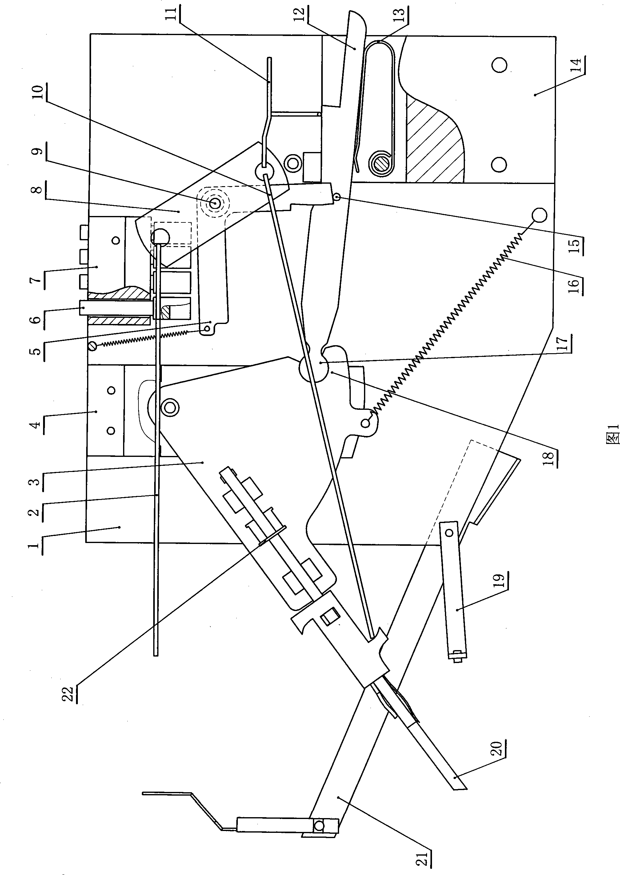
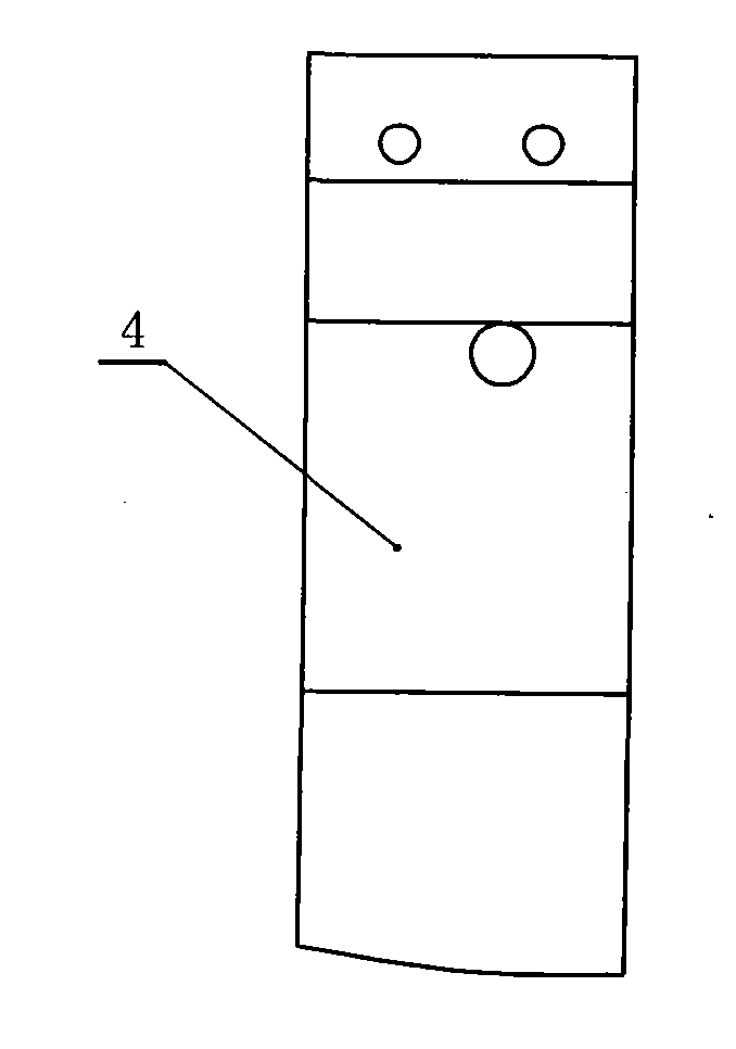
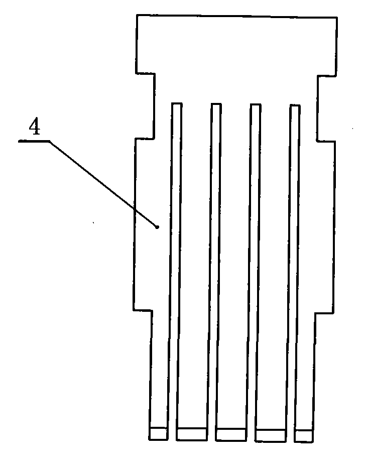
[0052] An automatic thread adjuster, such as figure 1 As shown, it includes an outer cover 1, and the outer cover 1 is fixedly equipped with a knife rest holder 4 (see figure 2 , image 3 ), yarn selection fixing seat 7, connecting seat 14 (see Figure 4 , Figure 5 ), yarn guide frame 19 (see Figure 24 ), yarn changing frame 21 (see Figure 25 , Figure 26 ), there is a through hole on the yarn selection holder 7, and the yarn selection rod 6 is plugged in the through hole (see Figure 20 ); There is a through groove on the connecting seat 14, and the tension spring 13 is installed in the through groove (see Figure 19 ); the outer cover 1 between the yarn selection fixed seat 7 and the connecting seat 14 is fixedly equipped with a main shaft, and the upper and lower ends of the main shaft are relatively rotated and are respectively sleeved...


PUM


Abstract

The invention relates to an automatic striping device with simple mechanism, low price and low failure rate, belonging to the textile mechanism. The automatic striping device comprises an outer casing, a tool-rest fixing seat which is fixedly arranged on the outer casing, a yarn-selection fixing seat, a connecting seat and a main shaft which is fixedly arranged between the yarn-selection fixing seat and the connecting seat on the outer casing. An upper end and a lower end of the main shaft oppositely revolve and are respectively sheathed with a collecting-cutting rotary block. An L-shaped control board is oppositely and rotationally sheathed between the upper and lower collecting-cutting rotary blocks on the main shaft. A groove is cut on the tool-rest fixing seat, a tool-rest board is oppositely and rotationally arranged in the groove, a tension-spring is connected with the tool-rest board and the other end of the tension-spring is fixed onto the outer casing. An arc-shaped connecting cut is arranged at the right end of the tool-rest board, and the rim of the connecting cut is greater than 50 percent of the arc. A link rod is connected in the connecting cut, the left end of the link rod is provided with a connecting head which is articulated with the connecting cut, and the connecting head and the connecting cut are on the same plane. The right end of the link rod clings to an expansion spring, and a resetting pin is arranged in the middle of the link rod and clings to the control board.

Description

technical field [0001] The invention relates to a thread regulator used in the textile industry, in particular to an automatic thread regulator. Background technique [0002] At present, all kinds of domestic knitting enterprises mainly use circular yarn-dyed jacquard circular knitting machines for production. Since the 1980s, with the in-depth development of my country's reform and opening up, domestic knitting enterprises have increased rapidly, and large circular knitting machines have become more and more popular among knitting enterprises. of favor. With the changes of the times, the automatic thread adjusters of large circular knitting machines produced by domestic circular knitting machine manufacturers are purchased from European countries such as Japan, Taiwan, and Germany with developed textiles. The thread adjusters produced in Japan and Taiwan are relatively small. , There are many parts, the internal space is small, and the failure rate is high, resulting in the...

Claims


Application Information

Patent Timeline
Patent Type & Authority Patents(China)
IPC IPC(8): D04B15/60D04B15/66
Inventor 冯发泉
Owner 冯发泉
Learn More