Impeller transmission structure of soldering tin stove
A transmission structure, soldering furnace technology, applied in the direction of assembling printed circuits with electrical components, can solve problems such as poor impeller stability, and achieve the effect of ensuring welding quality, smooth transmission, and ensuring stability
Inactive Publication Date: 2008-10-29
SUZHOU MINGFU AUTOMATIC SCI & TECH
View PDF0 Cites 0 Cited by
- Summary
- Abstract
- Description
- Claims
- Application Information
AI Technical Summary
Problems solved by technology
In order to overcome the problem of poor stability of the above-mentioned motor drive impeller, the present invention provides a soldering furnace impeller drive structure
Method used
View moreImage
Smart ImageViewing Examples


Examples
Embodiment Construction
Login to View More PUM
 Abstract
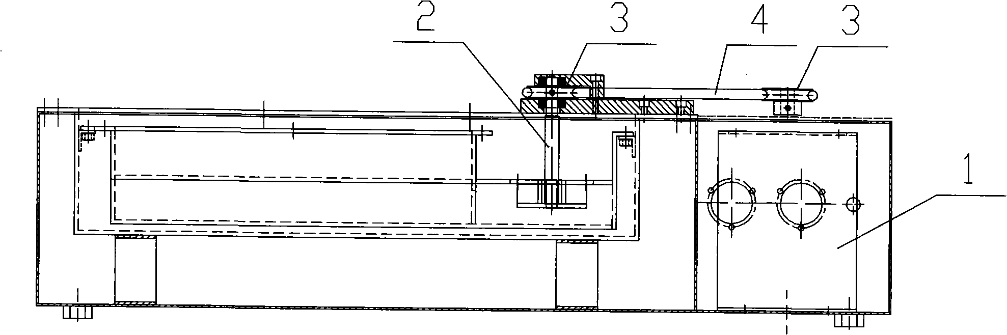
The invention relates to a soldering tin stove used for welding a PCB board, in particular to an impeller driving structure of the soldering tin stove. The structure comprises a motor and an impeller; driving wheels are arranged on a corresponding output shaft and a corresponding input shaft; leather belts are connected among the driving wheels; the leather belts are O-shaped rubber rings which are high-temperature resistant; the driving wheel comprises an inner wheel made of graphite and an outer wheel made of metal materials and used for wrapping the hub of the inner wheel. The structure of the invention effectively improves the influence of high temperature on the leather belts and a conveyor belt by changing the material of the leather belts and the driving wheels in the impeller driving structure, thus causing the driving of the motor to the impeller to be stable and guaranteeing the stability of tin wave generation and welding quality.
Description
A soldering furnace impeller drive structure technical field The invention relates to a soldering furnace used for PCB board welding, in particular to a soldering furnace impeller drive structure. Background technique Usually, when the motor is used to drive the impeller on the soldering furnace, the motor and the transmission wheel on the impeller shaft are connected by a belt, and the motor drives the impeller to rotate, so that the soldering furnace generates tin waves. However, there are still some deficiencies in this impeller drive structure: firstly, because the belt used is in a high-temperature environment for a long time, after a period of use, the pulley is prone to looseness and wear, which will affect the stability of the belt drive, and then In addition, the dust produced by the belt wear falls into the tin liquid, which will also affect the welding quality; secondly, the transmission wheel connected with the belt is usually made of metal material, and the me...
Claims
Login to View More Application Information
Patent Timeline
 Patent Type & Authority Applications(China)
IPC IPC(8): H05K3/34
Inventor 庄春明
Owner SUZHOU MINGFU AUTOMATIC SCI & TECH
Features
- R&D
- Intellectual Property
- Life Sciences
- Materials
- Tech Scout
- Unparalleled Data Quality
- Higher Quality Content
- 60% Fewer Hallucinations
Learn More Browse by: Latest US Patents, China's latest patents, Technical Efficacy Thesaurus, Application Domain, Technology Topic, Popular Technical Reports.
© 2025 PatSnap. All rights reserved.Legal|Privacy policy|Modern Slavery Act Transparency Statement|Sitemap|About US| Contact US: help@patsnap.com