Eureka AIR delivers breakthrough ideas for toughest innovation challenges, trusted by R&D personnel around the world.

LED lamp

A technology of LED lamps and aluminum alloys, applied in the cooling/heating devices of lighting devices, lighting and heating equipment, electrical components, etc., can solve the problem of unsatisfactory heat dissipation and achieve the effect of improving the service life

Inactive Publication Date: 2008-10-29
蒋仲林
View PDF0 Cites 6 Cited by
  • Summary
  • Abstract
  • Description
  • Claims
  • Application Information

AI Technical Summary

Problems solved by technology

Although it can also play a certain role in heat dissipation, its heat dissipation effect is not ideal.

Method used


Image

  • LED lamp

Examples


Embodiment Construction

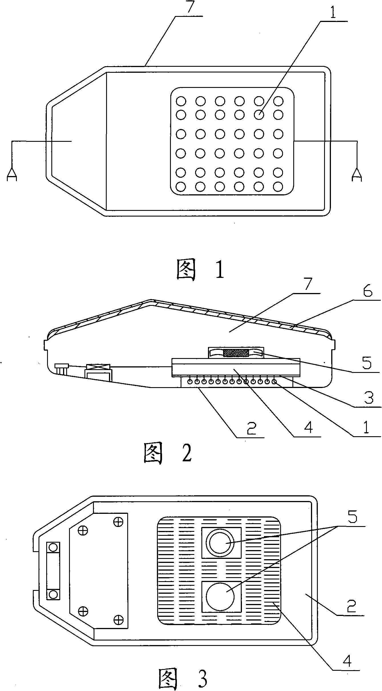
[0012] As shown in Figures 1 to 3, it is an LED lamp of the present invention, which consists of an LED illuminant 1, an explosion-proof tempered glass lampshade 2, an insulating paper pad 3, an aluminum alloy heat sink 4, a cooling fan 5, a thermal insulation layer 6 and The aluminum alloy shell 7 is composed, and the explosion-proof tempered glass lampshade 2 is installed under the LED illuminant 1, and the light is emitted through the lampshade, and the lampshade plays a protective role. The insulating paper is located between the luminous body and the aluminum alloy heat sink, which can prevent leakage and conduct heat. The aluminum alloy heat sink dissipates heat, and the two cooling fans installed behind it accelerate the dissipation of this heat. The heat insulation layer is set inside the aluminum alloy shell to prevent the intrusion of sunlight and heat.


PUM


Abstract

The invention discloses an LED lamp which includes an aluminum alloy casing, an LED illuminant arranged in the casing and an aluminum alloy cooling fin; at least a cooling fan is arranged at the rear part of the aluminum alloy cooling fin; and a thermal insulation layer is arranged on the inner lateral wall of the casing. The thermal insulation layer can be an aluminum alloy layer or a silica gel layer. The LED lamp can fully emit heat generated during the working process in a timely manner, and the heat of solar radiation can hardly enter, so that the service life is greatly prolonged.

Description

technical field [0001] The invention relates to an LED lamp. Background technique [0002] Due to its high luminous efficiency, no radiation and low power consumption, LED lights have become more and more popular since their appearance. With the advancement of science and technology, LED lights have also been continuously innovated and developed, and their advantages over other lighting methods have become more and more prominent. It can be predicted that the popularity of LED lights will continue to accelerate. However, during the development of LED lamps, there is always a problem that bothers its producers and users, that is, its heat dissipation. If the heat generated during the working process of the LED lamp is not dissipated in time, its life will be greatly affected. Existing LED heat dissipation generally adopts heat sinks to dissipate heat. Although it can also play a certain heat dissipation effect, its heat dissipation effect is not ideal enough. Contents o...

Claims


Application Information

Patent Timeline
IPC IPC(8): F21V29/00F21V29/02H01L33/00F21Y101/02F21V29/67F21V29/89F21Y115/10H01L33/64
Inventor 蒋仲林
Owner 蒋仲林
Why Eureka
Eureka Blog
Learn More