Wireless receiving apparatus and electronic appliance

A technology of wireless receiving device and electronic equipment, which is applied in the direction of TV, rebroadcast broadcasting device from a live rebroadcast unit, electrical components, etc., and can solve the problem of identifying each other between an undisclosed camera and a receiver

Inactive Publication Date: 2008-10-15
SONY CORP
View PDF3 Cites 1 Cited by
  • Summary
  • Abstract
  • Description
  • Claims
  • Application Information

AI Technical Summary

Problems solved by technology

[0016] Note that although Japanese Unexamined Patent Application Publication No. 2000-14037 and No. Heisei 11-215730 each disclose a technique for identifying whether a battery or a power adapter has been attached to a video camera, it has not been disclosed that the video camera and receiver technologies that recognize each other

Method used


Image

  • Wireless receiving apparatus and electronic appliance
  • Wireless receiving apparatus and electronic appliance
  • Wireless receiving apparatus and electronic appliance

Examples


Embodiment Construction

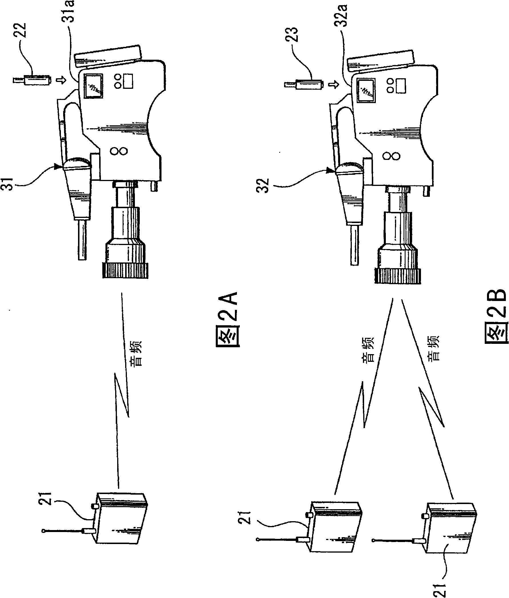
[0036] Preferred embodiments of the present invention will be described in detail below with reference to the accompanying drawings. Note that an example will be described in which an embodiment of the present invention has been applied to a multi-channel receiver similar to those described in Background Art and a camcorder compatible with the multi-channel receiver.

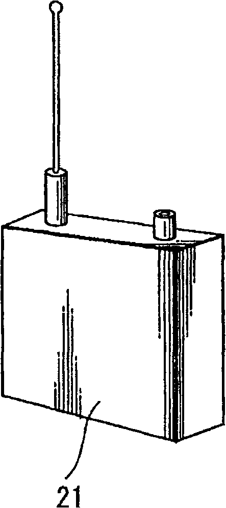
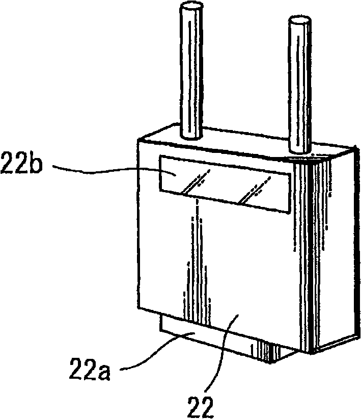
[0037]Fig. 3B is a diagram showing a circuit configuration of a part related to the present invention in a multi-channel receiver to which an embodiment of the present invention is applied. The receiver has a D-sub 15-pin connector (with Figure 1B Connector 22a of the shown receiver 22 corresponds to the connector) for outputting audio signals received on multiple channels, for inputting external power, and the like. The 7th pin P1 of the D-sub 15-pin connector is designated as a connected device identification terminal for identifying a camera connected to the D-sub 15-pin connector.

[0038] Note that exist...


PUM


Abstract

Disclosed is a wireless receiving apparatus. The wireless receiving apparatus includes a connector including a plurality of terminals a predetermined terminal of which is assigned as an identification terminal for identifying an electronic appliance connected to the connector, and a circuit for generating an identification signal of a level corresponding to a voltage level of the predetermined terminal when the electronic appliance is connected to the connector, and for identifying the electronic appliance connected to the connector based on the level of the identification signal.

Description

technical field [0001] The present invention relates to a wireless receiving device including a connector having a plurality of terminals and electronic equipment connected to the wireless receiving device using the connector having a plurality of terminals. Background technique [0002] In recent years, in the field of television broadcasting, it has become common to record audio transmitted using wireless microphones. Figure 1A and Figure 1B An example of the appearance of a wireless microphone is shown. In these figures, Figure 1A A wireless microphone transmitter (hereinafter simply referred to as "transmitter") is shown as a means for transmitting audio. The transmitter 21 transmits radio waves modulated by an audio signal from a microphone. [0003] Figure 1B A wireless microphone receiver (hereinafter simply referred to as "receiver") is shown as a means for receiving audio. The receiver 22 receives radio waves transmitted from the transmitter 21, and demodula...

Claims


Application Information

Patent Timeline
Patent Type & Authority Applications(China)
IPC IPC(8): H04N5/222H04H20/04
CPCH04B1/034
Inventor 山木俊之铃木浩之阿部淳生
Owner SONY CORP
Why Eureka
Try Eureka