Method for non-contact dynamic detection of solid contour

A dynamic detection and non-contact technology, which is applied in the direction of measuring devices, optical devices, instruments, etc., can solve the problems of unreliable measured values, distortion of the surface to be measured, and inability to obtain measured values, so as to reduce hardware expenditure, Effect of reduced hardware outlay, reduced time to set up and calibrate measurement equipment

Inactive Publication Date: 2008-10-08
GUTEHOFFNUNGSHUTTE RADSATZ
View PDF1 Cites 10 Cited by
  • Summary
  • Abstract
  • Description
  • Claims
  • Application Information

AI Technical Summary

Problems solved by technology

[0004] In practice, however, the problem that arises in this case is that the movement of the surface to be measured and the possible curvature cause distortion, which must be counteracted by a correction of the measured value, otherwise the measured value corresponding to the real situation will not be obtained
[0005] In this case, the moment of detection of the measured value also plays an important role, since an incorrect choice of this moment can lead to the measured value being no longer plausible even after correction

Method used


Image

  • Method for non-contact dynamic detection of solid contour
  • Method for non-contact dynamic detection of solid contour
  • Method for non-contact dynamic detection of solid contour

Examples


Embodiment Construction

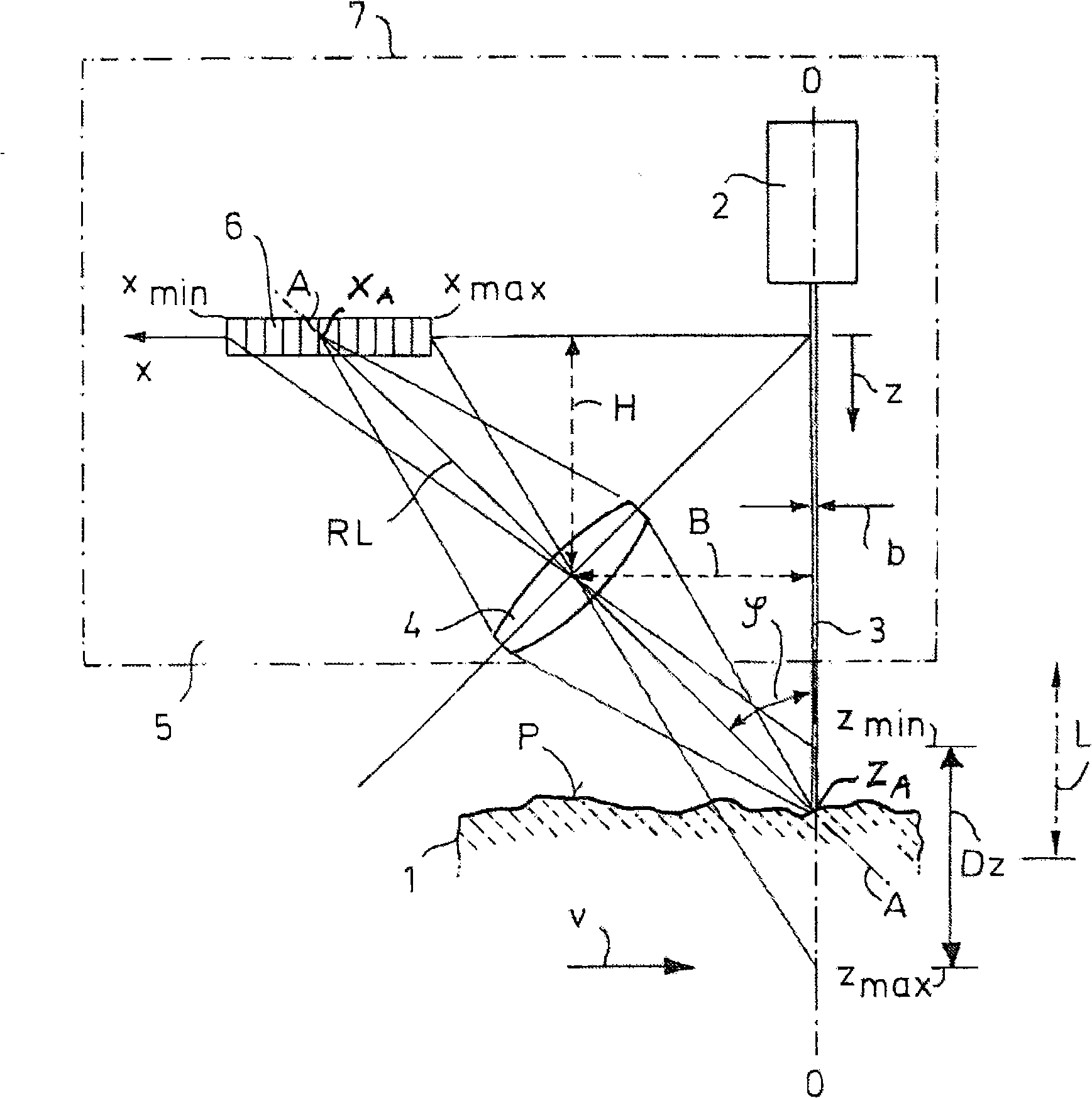
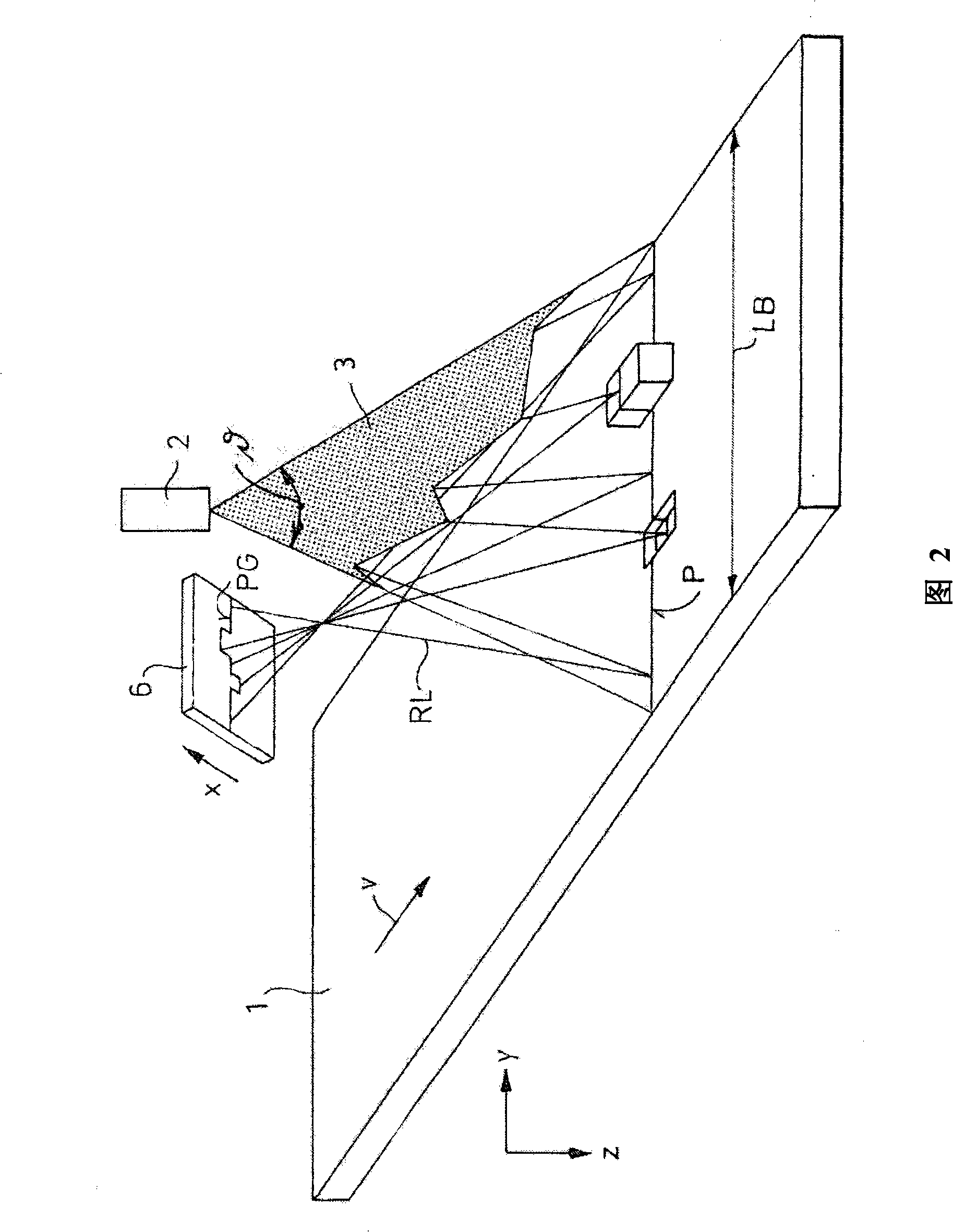
[0072] first as figure 1 As shown in the two-dimensional schematic diagram of the object to be measured, a solid 1 is moving at a velocity v. According to the principle on which the method of the present invention is based, a beam of light emitted from a laser 2 is focused by an optical element (not shown) so that the The width b of the beam falls within a specified range in the measuring range Dz consisting of a maximum measurable value z of the depth or profile height z max with a minimum z min resulting from the difference between. In this case, the light beam is spread out to form a light strip 3 as shown in the three-dimensional representation in FIG. 2 .

[0073] The incident position z of the light band on the surface of solid 1 A The diffuse light scattered there (reflected light RL) forms a measurement spot which is also perceivable in directions deviating from the direction of incidence determined by the optical axis 0-O of the laser 2 .

[0074] If the measureme...


PUM


Abstract

The invention relates to a method for contactless dynamic detection of the profile of a solid body (1), wherein at least one light beam which is generated by a laser device (2) and is expanded to form at least one linear light band (3) is projected onto the moving surface of the solid body (1) and the light reflected from the surface of the solid body (1) is focused in an imaging device (5), the optical axis of which is at a fixed triangulation angle with respect to the projection direction of the laser device (2) and which is arranged at a fixed basic distance from the laser device (2), and is detected by means of an areal light recording element (6), after which, from signals emitted by the light recording element (6), in a manner dependent on the triangulation angle and the basic distance, in a data processing device,; by means of trigonometrical relationships and with combination with correction values determined according to the speed of movement of the solid body (1), the measured values of the profile are obtained and stored as a profilogram. It is proposed to perform a determination of initial conditions of the solid body (1) at an initial instant and then to determine a detection instant from the initial conditions.

Description

technical field [0001] The invention relates to a method for the contactless dynamic detection of solids, in particular the contours of moving solids, wherein a laser beam from a laser is projected onto an area of ​​the solid surface in the form of a linear band of light, and Light reflected from it is focused to an imaging device whose optical axis is at a fixed triangulation angle to the laser and placed at a fixed pedestal distance from the laser, and passed through a planar light-receiving element to communicate with the laser. The speed of motion of the solid is detected at a frequency that is high, so that the signal output by the light-receiving element is used in a data processing device as a function of the triangulation angle and the base distance, so that by geometric relationship to obtain measurements of the contour, which are stored as a contour map. Background technique [0002] It is known that detecting the contour of a solid body, that is to say obtaining ...

Claims


Application Information

Patent Timeline
Patent Type & Authority Applications(China)
IPC IPC(8): G01B11/24
CPCG01B11/2522
Inventor 曼弗雷德·霍夫曼克里斯蒂安·诺沃齐克米夏埃多·J·瓦尔特安德烈亚斯·布林克曼迪特尔·霍夫曼
Owner GUTEHOFFNUNGSHUTTE RADSATZ
Why Eureka
Try Eureka