
Method for changing energize mode to realize different mode electromagnetic detection

A technology of electromagnetic detection and excitation mode, applied in the direction of material magnetic variables, etc., can solve the problems of inconvenience, high cost of instrument production, unsuitable detection of deep layers of metal materials, etc., and achieve the effect of convenient use

Active Publication Date: 2008-10-08
林俊明
View PDF0 Cites 19 Cited by
  • Summary
  • Abstract
  • Description
  • Claims
  • Application Information

AI Technical Summary

Problems solved by technology

[0007] Because various electromagnetic detection methods have their own different characteristics, such as eddy current detection is more suitable for the detection of metal pipes, rods, and materials, and has a high detection sensitivity for surface defects, but it is not suitable for detecting internal defects in deep layers of metal materials. , so in the application process, it is necessary to have detection devices corresponding to various methods, such as eddy current detectors based on the principle of eddy current detection, magnetic memory detectors based on the principle of magnetic memory detection, and magnetic detectors based on the principle of magnetic flux leakage detection. Magnetic flux leakage detector, etc.
Whether eddy current testing, magnetic memory testing or magnetic flux leakage testing is used, the defect signals of the tested parts are usually obtained by using their own probes or sensors, and the defects of the tested parts are displayed through corresponding data processing and analysis methods. Due to different electromagnetic detection methods, different detection instruments and sensors are required, which brings great inconvenience to people's use, and also makes the production cost of the instrument higher.

Method used


Image

  • Method for changing energize mode to realize different mode electromagnetic detection
  • Method for changing energize mode to realize different mode electromagnetic detection
  • Method for changing energize mode to realize different mode electromagnetic detection

Examples


Embodiment Construction

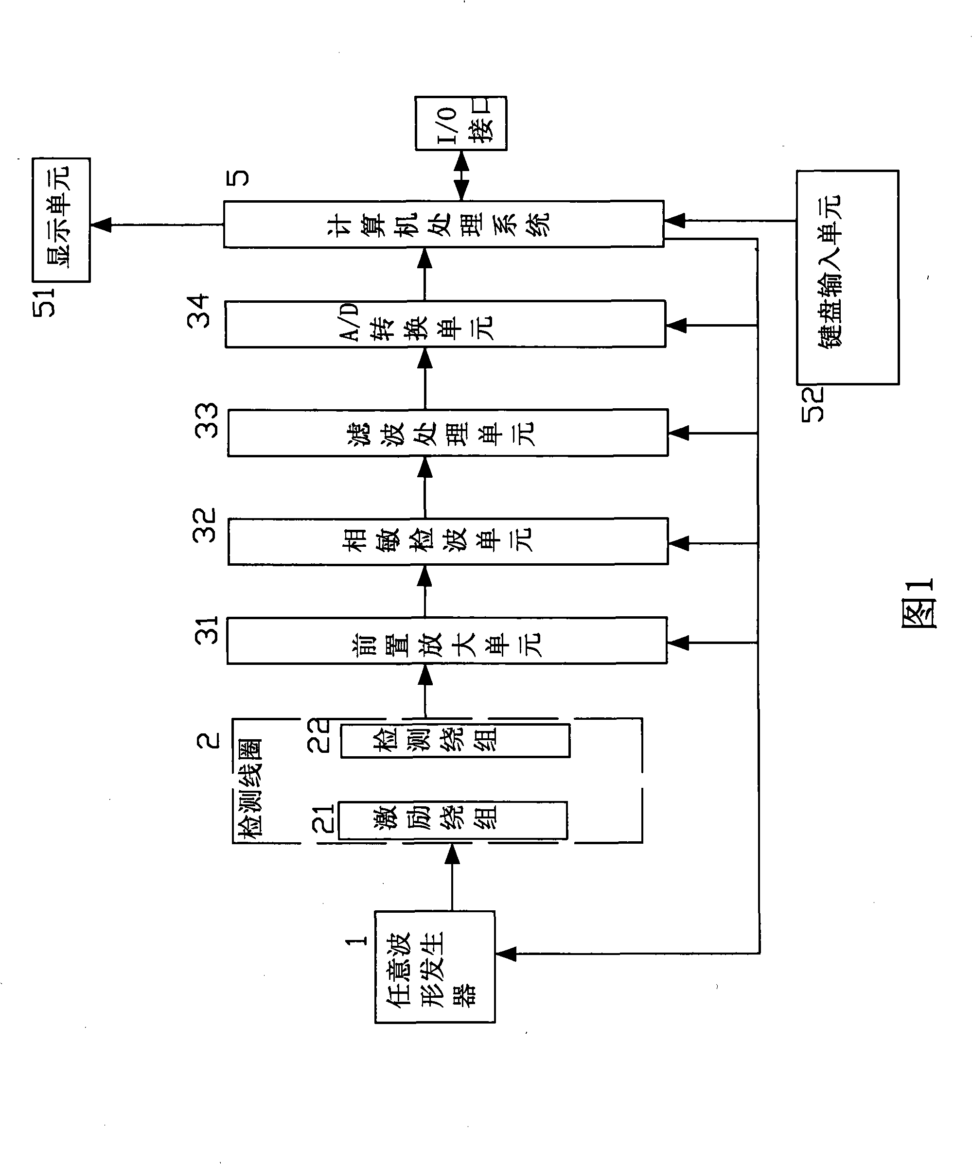
[0036] Referring to the accompanying drawings, a method for realizing electromagnetic detection in different ways by changing the excitation mode of the present invention can be realized by the following devices, such as an arbitrary waveform generator 1, a detection coil 2, and a preamplifier unit 31 , phase-sensitive wave detection unit 32, filter processing unit 33, A / D conversion unit 34, computer processing system 5, display unit 51, keyboard input unit 52, arbitrary waveform generator 1 is controlled by computer processing system 5, the detection coil 2 The excitation winding 21 is connected to the output of the arbitrary waveform generator 1, the output of the detection winding 22 of the detection coil 2 is connected to the input of the preamplifier unit 31, and the output of the preamplifier unit 31 is connected to the input of the phase sensitive detection unit 32, and the phase The output of the sensitivity detection unit 32 is connected to the input of the filter pro...


PUM


Abstract

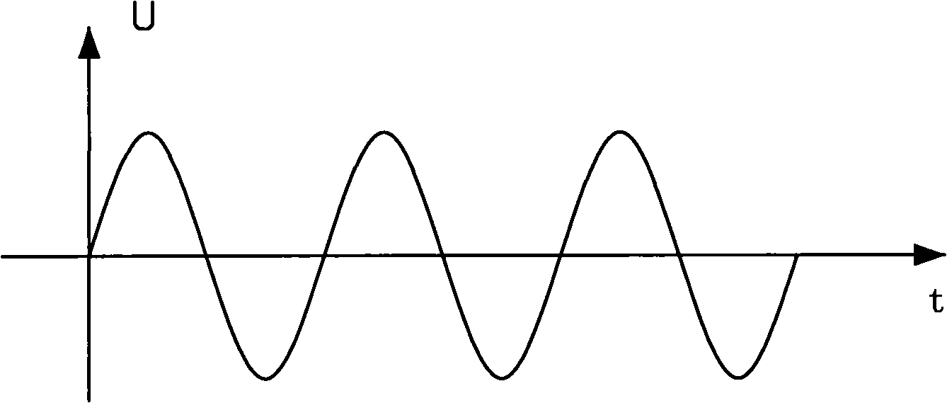
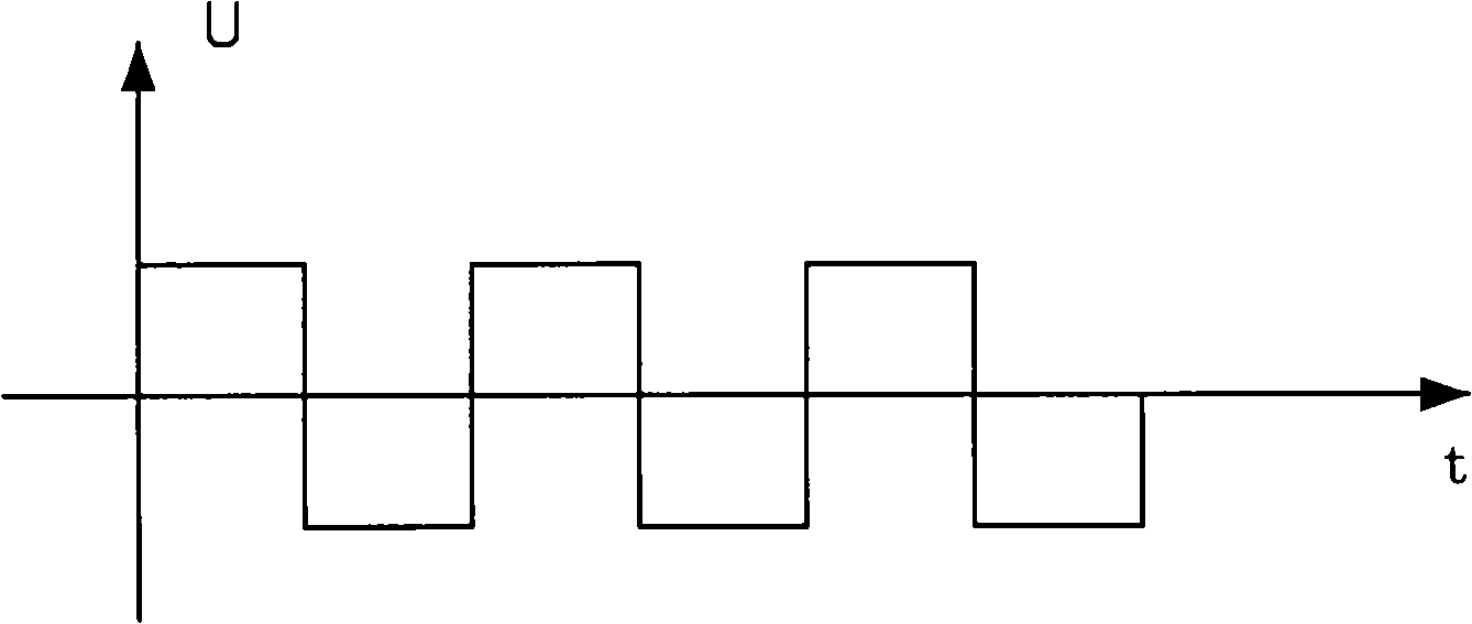
The invention discloses a method which realizes electromagnetic testing in different ways through changing motivation models. Wherein, a sensor is imposed with different motivation models: a sine wave motivation is imposed when carrying out eddy current testing, a square wave motivation is imposed when carrying out magnetic flux leakage, and a high duty ratio pulse motivation is imposed when carrying out magnetic memory testing, then the sensing signals obtained in different motivation models are carried out different analysis and processing so as to obtain different detection parameters, thereby the invention not only can respectively realize single eddy current testing or magnetic flux leakage or magnetic memory testing according to the requirements of different components to be detected, but also can obtain the detection parameters of eddy current testing, magnetic flux leakage, and magnetic memory testing through time-sharing detection according the requirement of the same component to be detected. Thus, the invention brings great convenience for people and greatly reduces the production cost of the detector.

Description

technical field [0001] The invention relates to a non-destructive testing method, in particular to a method for realizing electromagnetic testing in different modes by changing excitation modes. Background technique [0002] Non-destructive testing NDT (nondestructive test) is a technology that detects its performance, quality, and internal defects without destroying or damaging the object under test. [0003] Electromagnetic testing technology belongs to non-destructive testing technology. Electromagnetic testing is a test method that uses the electrical and magnetic properties of materials under electromagnetic action to judge the performance of materials. Electromagnetic testing technology has been widely used in various industrial fields, especially This is especially true in manufacturing, aerospace, petrochemical and other fields. The methods based on electromagnetic detection principles in the prior art mainly include conventional eddy current detection methods, far-...

Claims


Application Information

Patent Timeline
Patent Type & Authority Applications(China)
IPC IPC(8): G01N27/82
Inventor 林俊明
Owner 林俊明
Learn More