
Biomass shaping fuel decoupling combustion device and combustion method thereof

A technology of briquetting fuel and combustion device, which is applied in the field of biomass briquetting fuel decoupling combustion device and its combustion, can solve the problems of weak combustion of volatile matter and semi-coke, high requirements on fuel fluidity, unfavorable semi-coke burnout, etc. , to achieve the effect of reducing the coupling relationship, reducing the pollutant content and improving the combustion efficiency

Inactive Publication Date: 2008-09-24
INST OF PROCESS ENG CHINESE ACAD OF SCI
View PDF2 Cites 16 Cited by
  • Summary
  • Abstract
  • Description
  • Claims
  • Application Information

AI Technical Summary

Problems solved by technology

However, the double-layer inclined grate used in this device has high requirements on the fluidity of the fuel, and because a large amount of volatile matter generated will directly enter the combustion chamber from the communication hole opened on the partition plate for combustion, the volatile matter and semi-coke are combusted together. The degree is weak, which is not conducive to the burnout of semi-coke with low calorific value; in addition, the organization of primary air, secondary air and tertiary air in the combustion furnace is difficult to achieve in small combustion equipment

Method used


Image

  • Biomass shaping fuel decoupling combustion device and combustion method thereof
  • Biomass shaping fuel decoupling combustion device and combustion method thereof
  • Biomass shaping fuel decoupling combustion device and combustion method thereof

Examples


Embodiment 1

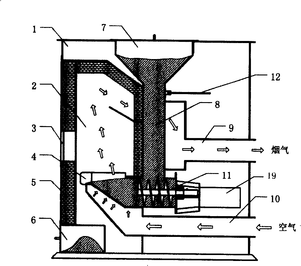
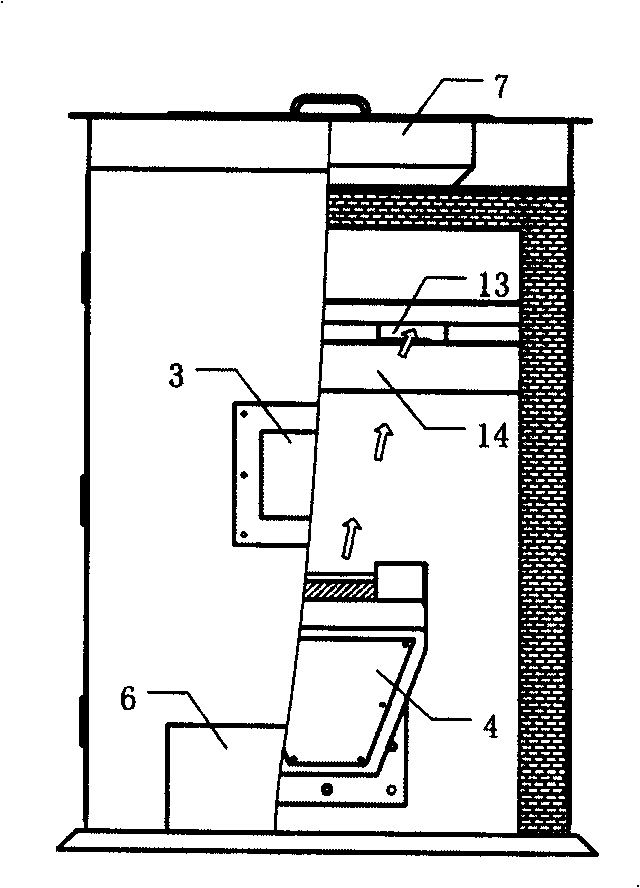
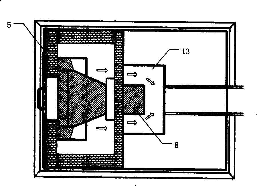
[0043] The biomass briquette fuel decoupling combustion device of this embodiment, as shown in Figure 1, includes: a vertical combustion furnace 1, a hopper 7 is arranged above the furnace body, and the lower part of the hopper 7 is connected to a pyrolysis chamber 8 with a rectangular cross section , the bottom of the pyrolysis chamber 8 is provided with a screw conveyor 11, and the lower part of the pyrolysis chamber communicates with the lower part of the combustion chamber 2, the combustion chamber 2 is adjacent to the pyrolysis chamber 8, and the lower part of the combustion chamber 2 is provided with Fire grate 4, an air duct 10 is provided below the fire grate 4, and the screw conveyor 11 transports the biomass molding fuel pyrolyzed in the pyrolysis chamber 8 to the fire grate 4, as shown in Figure 1, the combustion A flue gas deflector 14 is arranged above the interior of the chamber 2, and the upper part of the flue gas deflector 14 communicates with the flue gas inte...

Embodiment 2

[0051] The method for burning using the biomass briquette fuel decoupling combustion device in embodiment 1 comprises the steps:

[0052] (1) Biomass molding fuel enters the pyrolysis chamber 8 from the hopper 7, and the temperature in the pyrolysis chamber 8 can reach 300-800 °C by utilizing the heat in the combustion chamber 2 and the waste heat of the flue gas flowing through the flue gas interlayer 13 outside the pyrolysis chamber 8 °C, the biomass briquettes in the pyrolysis chamber 8 are slowly pyrolyzed under low temperature and oxygen-free conditions to generate volatiles and semi-coke;

[0053] (2) The biomass semi-coke produced by pyrolysis enters the upper surface 15 of the fire grate 4 under the conveyance of the screw conveyor 11, and contacts with the air sent in from the air chamber 17 below the fire grate 4 and the side air supply port 16 Combustion begins after the pyrolysis, and when the volatile matter generated by pyrolysis enters the combustion chamber 2, ...


PUM


Abstract

The invention relates to a decoupling combustion device for the biomass briquetting fuel and the combustion method. The device comprises a vertical combustion furnace, a combustion chamber and a pyrolysis chamber; the bottom of the combustion chamber is communicated with the bottom of the pyrolysis chamber; a hopper is mounted on top of the pyrolysis chamber; a gate is mounted at the lower part of the combustion chamber. The invention is characterized in that a screw conveyor is mounted at the lower part of the pyrolysis chamber; a flue gas interlayer is mounted on the outside wall of the pyrolysis chamber, which is communicated with a flue gas channel at the lower part of the furnace body; an air duct is mounted at the lower part of the gate; a flue gas baffle is mounted in the combustion chamber; the upper part of the flue gas baffle is communicated with the flue gas interlayer. The method is combined with the combustion characteristic of the biomass briquetting fuel, which processes the pyrolysis and the combustion of the biomass briquetting fuel respectively in two areas with different temperature; the method alleviates the contradiction that the pyrolysis speed does not match with the combustion speed; the method eliminates the coupling of different pollutants in the generation process, reduces the loss of incomplete combustion and decreases the discharging amount of the pollutants such as CO and NOx through the re-organization of the combustion of the volatile and the char.

Description

technical field [0001] The invention relates to a combustion device and a combustion method of biomass briquette fuel, in particular to a decoupled combustion that can reduce the emission of soot, nitrogen oxides and carbon monoxide from combustion of biomass briquette fuel, and improve the utilization efficiency of biomass briquette fuel Apparatus and combustion method thereof. Background technique [0002] Biomass is a renewable energy source that does not increase CO in the atmosphere during utilization 2 net emissions, reducing the greenhouse effect. With the lack of fossil energy and the enhancement of environmental awareness, the efficient and clean utilization of biomass has attracted much attention. my country is rich in biomass energy, but the volume density of biomass is small, the stacking volume is large, storage and transportation are difficult, and the biomass has a lot of volatile matter, so the combustion of coke and volatile matter are not synchronized, an...

Claims


Application Information

Patent Timeline
Patent Type & Authority Applications(China)
IPC IPC(8): F23G5/027
Inventor 董利高士秋郝江平许光文李静海
Owner INST OF PROCESS ENG CHINESE ACAD OF SCI
Learn More