
A current-adjustable charge pump circuit

A current regulation circuit, charge pump technology, applied in the direction of electrical components, automatic power control, etc., can solve the problems of inconvenient adjustment, reduction of current size, unfavorable loop control, etc.

Inactive Publication Date: 2008-09-17
东莞润风电子科技有限公司
View PDF0 Cites 8 Cited by
  • Summary
  • Abstract
  • Description
  • Claims
  • Application Information

AI Technical Summary

Problems solved by technology

If the current of the charge pump circuit is fixed, the oscillation frequency of the charge pump phase-locked loop can only be adjusted by adjusting the loop filter or the voltage-controlled oscillator, but the transfer function of the entire phase-locked loop will change greatly, which is not conducive to the overall The control and adjustment of the loop is very inconvenient; if the current in the charge pump circuit is changed by changing the width and length of the current mirror tube, it can only be achieved by increasing the number of current mirror tubes connected in parallel on the basis of the original reference current source. Increase the size of the current, but cannot reduce the size of the current, and each modification also needs to involve the modification of the layout, which is also very inconvenient

Method used


Image

  • A current-adjustable charge pump circuit
  • A current-adjustable charge pump circuit
  • A current-adjustable charge pump circuit

Examples


Embodiment Construction

[0029] The specific implementation of the present invention will be further described below in conjunction with the accompanying drawings.

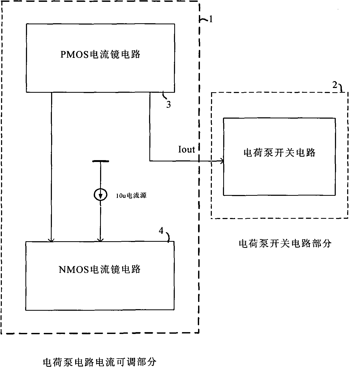
[0030] figure 1 For the block circuit diagram of structure of the present invention, see figure 1 , the present invention includes a charge pump current regulation circuit 1 and a charge pump switch circuit 2, a 10uA external current source is connected to the current input terminal of the charge pump current regulation circuit 1, and the current output terminal of the charge pump current regulation circuit 1 is connected to the charge pump switch circuit 2 connected to charge or discharge the charge pump output node through the charge pump switch circuit 2.

[0031] The charge pump current regulation circuit 1 includes an NMOS current mirror circuit 4 and a PMOS current mirror circuit 3, the current input terminal of the NMOS current mirror circuit 4 is connected to the external current source, and the current output terminal of the NMO...


PUM


Abstract

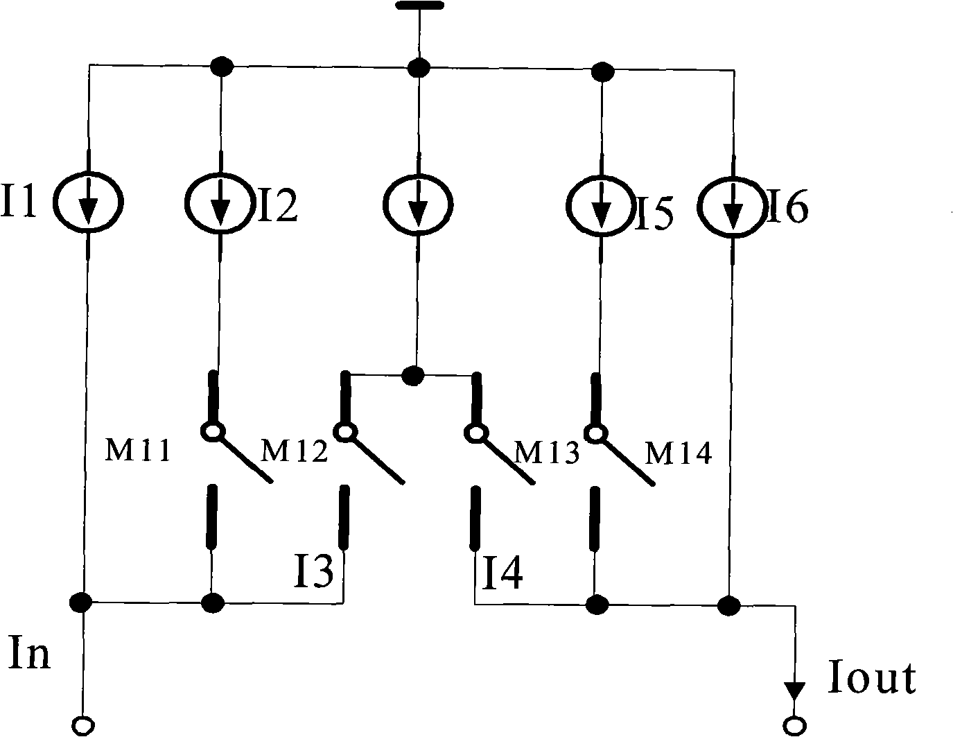
A current-adjustable charge pump circuit comprises a charge pump current regulating circuit which is connected to the external current source and a charge pump switching circuit connected with the charge pump current regulating circuit. The invention is characterized in that the charge pump current regulating circuit is composed of a NMOS current mirror circuit and a PMOS current mirror circuit which are connected. The NMOS current mirror circuit and PMOS current mirror circuit are respectively composed of a current mirror source tube branch line and a current mirror image tube branch line which are correspondingly connected with a switching tube. A relatively-fixed proportional dimension is provided between the mirror source tube and the mirror image tube on the corresponding branch line. The number of the mirror source branch line or the mirror image branch line is selected through the controlling of the control signal to the on-off of the control switching tube, thereby the output currents of the NMOS current mirror circuit and PMOS current mirror current are changed. The regulation to the charging current and discharging current of the charge pump is realized through the charge pump switching circuit. The invention not only can conveniently and smartly regulate the current of the charge pump, but also can regulate to obtain a current which has a relationship that the current is a fractional part of the input current source.

Description

technical field [0001] The invention relates to a charge pump circuit, in particular to a charge pump circuit with adjustable current, which is mainly applied to a charge pump integrated module in an integrated phase-locked loop. Background technique [0002] The application of the charge pump phase-locked loop is very extensive. Generally speaking, the charge pump in the phase-locked loop is composed of two current sources with switches, and the output of the pre-stage frequency or phase detector (PFD) determines the switch. The opening and closing of the circuit, so as to decide whether to pump the charge into the loop filter of the subsequent stage or pump the charge out of the loop filter of the subsequent stage, and the resulting control voltage (vctrl) to control the post-stage loop filter stage voltage controlled oscillator (vco). The reason why the current of the charge pump circuit is adjustable is to flexibly adjust the above-mentioned control voltage (vctrl), so ...

Claims


Application Information

Patent Timeline
IPC IPC(8): H03L7/08H03L7/099
Inventor 程雯褚炜路
Owner 东莞润风电子科技有限公司
Learn More