A rotor for DC electromotor

A DC motor and rotor technology, applied in the field of motor manufacturing, can solve the problems of increasing harmful additional dynamic loads, decreasing motor efficiency, and uneven rotation speed, achieving obvious power saving effects, reducing additional resistance loads, and overcoming low torque. zone effect

Inactive Publication Date: 2008-09-17
ZHEJIANG QIANGYU ECONOMY & TRADE
View PDF0 Cites 0 Cited by
  • Summary
  • Abstract
  • Description
  • Claims
  • Application Information

AI Technical Summary

Problems solved by technology

The above situation will inevitably lead to unsmooth speed. When the load is applied, the running vibration of the motor will inevitably occur. This will increase the harmful additional dynamic load and do more useless work, thus leading to a decrease in the efficiency of the motor.
This is also the problem of low efficiency, high power consumption, and short range of electric vehicles currently using DC motors as power devices.

Method used


Image

  • A rotor for DC electromotor

Examples


Embodiment Construction

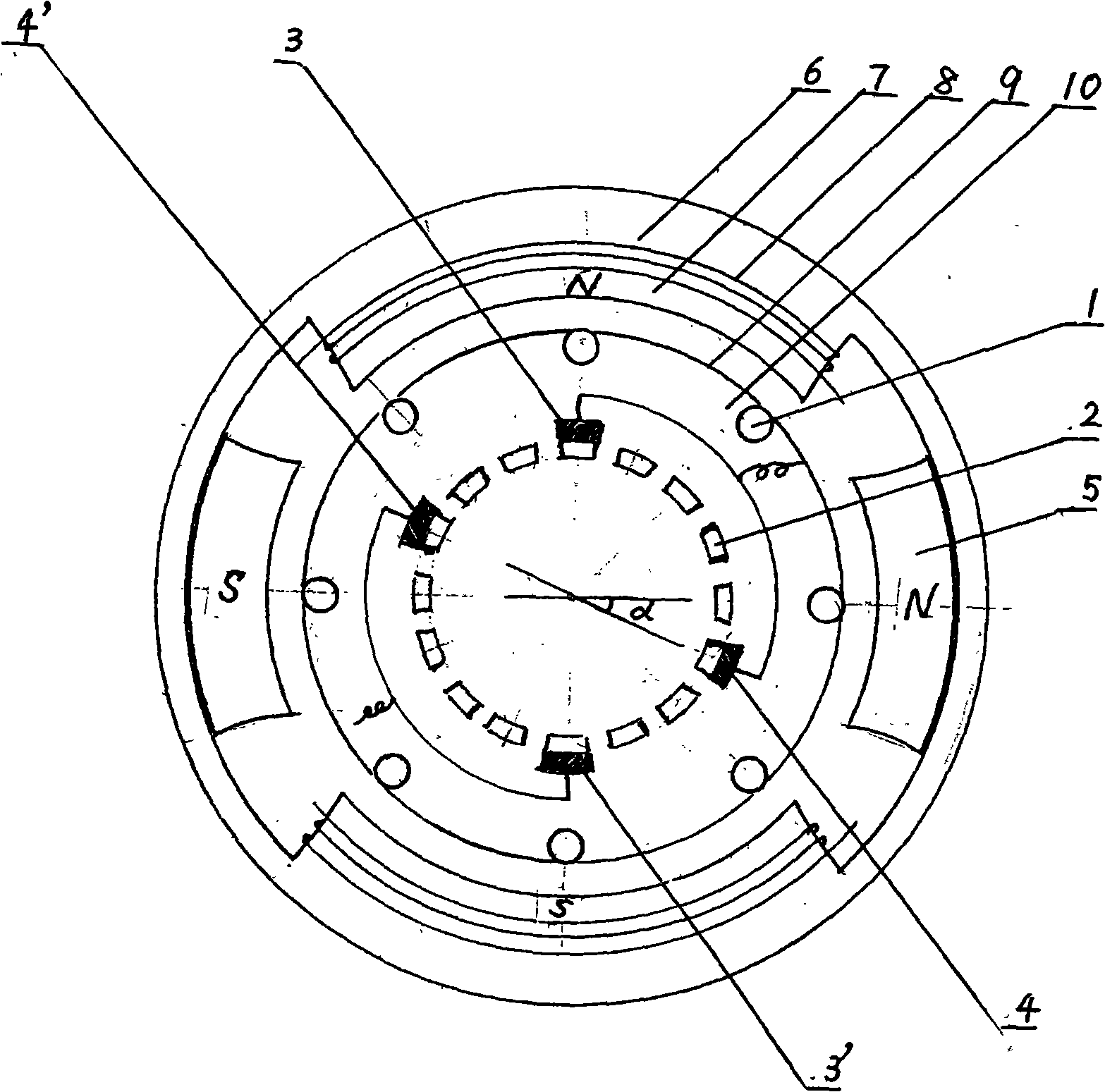
[0008] The present invention is mainly composed of a rotor core 10, a coil 1 with a current commutation piece 2, a pair of commutation carbon brushes 3, 3' placed on the current commutation piece 2, and a pair of passing carbon brushes 4, 4', etc. , one reversing carbon brush 3 is connected with the adjacent passing carbon brush 4, and the other reversing carbon brush 3' is connected with another adjacent passing carbon brush 4'; the straight line of the reversing carbon brush 3, 3' The angle between the straight line passing through the adjacent carbon brushes 4, 4' is 91°-95° ​​in the clockwise direction.

[0009] The rotor 9 of the above-mentioned structure is matched with the stator 6 formed by the stator core 7, the permanent magnet 5 and the winding 8. When used on an electric car, the speed per hour can be changed from the original average to the same under the condition of the vehicle condition, road condition, load and battery capacity. 30KM, the highest 40KM, increas...


PUM


Abstract

The present invention provides a rotor for DC motor, belonging to motor manufacture technical field, mainly composed of a rotor core, a coil having a current commutation plate, a pair of commutation carbon brushes placed on the current commutation plate and a pair of over carbon brushes, one commutation brush is connected with the adjacent over carbon brush, the other commutation brush is connected with the adjacent the other over carbon brush; the intersecting angle of the line of the commutation brush and the line of the adjacent over carbon brush is 91-95 degree clockwise. The structure design is more reasonable and scientific, the change of the current commutation angle is matched and adapted with the stator magnetic field after forming DC motor with the stator, effectively enhancing and changing the distribution condition of the magnetic density, overcoming the lower torque zone, changing the motor output characteristic, effectively reducing the additional resistance load, having evident saving effect.

Description

technical field [0001] The invention relates to a rotor for a DC motor, which belongs to the technical field of motor manufacturing. Background technique [0002] There are small and medium power DC motors widely used in electric vehicles, light industrial products, and household appliances, or carbon brush commutation motors with parallel excitation, series excitation or complex excitation. In this way, the torque generated by the rotor coil at different angular positions in the magnetic field is different and alternates. Taking a single-turn rectangular planar coil as an example, when the coil plane is perpendicular to the magnetic field, the coil will not generate a rotational moment, and the coil will rotate by inertia. The above situation will inevitably lead to unsmooth speed. When the load is applied, the running vibration of the motor will inevitably occur. This will increase the harmful additional dynamic load and do more useless work, thus resulting in a decrease ...

Claims


Application Information

Patent Timeline
Patent Type & Authority Applications(China)
IPC IPC(8): H02K23/02H02K23/20
Inventor 王建强唐明辉高新福张歧良宣汉强王炼强
Owner ZHEJIANG QIANGYU ECONOMY & TRADE
Why Eureka
Try Eureka