Laser synthetic aperture radar image-forming range direction phase compensation process

An aperture radar and phase compensation technology, applied in the field of radar, can solve the problems of unstable laser waveform echo phase and error, and achieve the effects of accurate compensation, simple form and simple search process

Inactive Publication Date: 2008-09-17
XIDIAN UNIV
View PDF0 Cites 19 Cited by
  • Summary
  • Abstract
  • Description
  • Claims
  • Application Information

AI Technical Summary

Problems solved by technology

[0004] The purpose of the present invention is to apply W. Buell's thought, propose a kind of laser synthetic aperture radar imaging distance direction phase compensation method, to solve the echo phase error problem caused by the instability of the laser waveform, so that the echo after compensation Well compressed in distance up

Method used


Image

  • Laser synthetic aperture radar image-forming range direction phase compensation process
  • Laser synthetic aperture radar image-forming range direction phase compensation process
  • Laser synthetic aperture radar image-forming range direction phase compensation process

Examples


Embodiment Construction

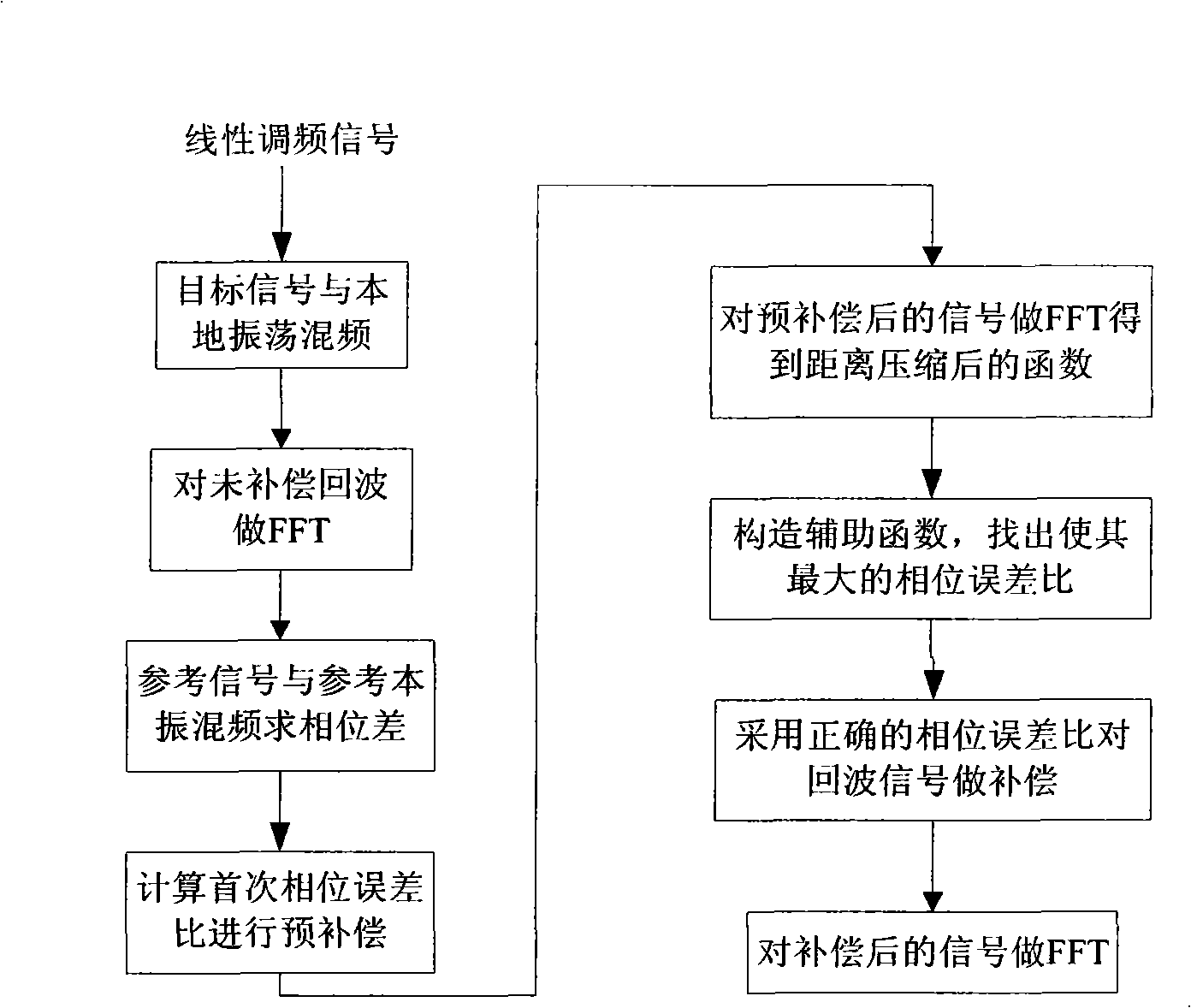
[0025] refer to figure 1 , the compensation process of the present invention is as follows:

[0026] 1. Perform frequency difference on the chirp signal.

[0027] The chirp signal includes: target signal, target local oscillator, reference signal and reference local oscillator signal.

[0028] 1. The general form of the chirp signal generated by the tunable laser is:

[0029] s ( t ^ , t m ) = rect ( t ^ T p ) e j 2 π ( f c t + 1 2 ...


PUM


Abstract

The invention discloses a method of compensating the laser aperture composed radar imaging distance to phase. The method comprises: respectively performing the difference frequency to the target path of the laser aperture composed radar and the target local oscillator path, the reference channel and the reference local oscillator path to obtain echo after difference frequency; calculating the first phase error ratio p(taux) of the target echo based on the second phase of the echo after difference frequency; precompensation the phase error using the p(taux) and constructing the auxiliary function S(p(taux)); obtaining the corresponding phase error ratio p'(taux) by the auxiliary function and compensating and compressing the distance of the target echo signal to the phase error. The invention solves the problem of echo phase error due to instability of the laser waveform, therefore the compensated echo is compressed in the azimuth direction.

Description

technical field [0001] The invention belongs to the technical field of radar and relates to imaging technology, in particular to a phase compensation method for laser aperture synthetic radar imaging range direction. Background technique [0002] The formation of a synthetic aperture lidar image requires the measurement of the phase change process of the returned lidar signal during the formation time of the synthetic aperture. This process is completed by coherent detection, that is, the laser echo signal is mixed with a stable local oscillator signal to realize the demodulation of the echo signal. Due to the large bandwidth of the chirp signal, the sampling rate must be at least 4THz to satisfy the Nyquist sampling interval. Current analog-to-digital converters cannot handle such a large bandwidth, so the echo signal is demodulated by mixing it with a copy of the transmitted signal. However, the waveform of the LFM laser is not ideally linear, and the waveform between pu...

Claims


Application Information

Patent Timeline
IPC IPC(8): G01S7/497G01S17/89
Inventor 郭亮邢孟道郭睿保铮
Owner XIDIAN UNIV
Why Eureka
Try Eureka