Cylinder type gas heating stove improvement structure

A technology of gas heating and improved structure, which is applied in the direction of air heaters, fluid heaters, heat storage heaters, etc., which can solve the problem of reducing the effective use of the heating surface and the heating surface, unable to realize the user's convective heat transfer mode, and not conducive to energy saving Consumption reduction and environmental protection and other issues, to achieve the effect of simple structure, easy promotion and use, and small investment

Inactive Publication Date: 2011-07-06
SHANGHAI UNIV OF ENG SCI
View PDF2 Cites 0 Cited by
  • Summary
  • Abstract
  • Description
  • Claims
  • Application Information

AI Technical Summary

Problems solved by technology

[0008] a. Because the temperature of the medium close to the wall of the fire tube and the smoke tube bundle is high, an upward flow will be formed, while the temperature of the medium near the heated tube bundle is relatively low, and a downward flow will be formed, because there is no proper flow path for the intermediate heat-carrying medium In addition, there is a temperature difference between the fire tube and the smoke tube bundle, and there is a temperature difference between the multiple returns of the heated tube bundle, all of which lead to the disorder of the flow field organization in the large cylinder, resulting in uneven heating in the large cylinder. uniform; b. Due to the small temperature difference between the upper and lower sides of the flow field, the power of natural convection is also small, which makes it difficult to form an effective flow field, and the convective heat transfer between the heating surface and the heating surface in the large cylinder is very weak; c. In the entire flow field In the field, there are still many flow dead angles, such as the bottom of the large cylinder, etc.
All these factors will destroy the effective heat transfer flow field in the large cylinder, reduce the effective utilization of the heating surface and the heating surface, thereby reducing the efficiency of the natural gas heating furnace and high energy consumption, which is not conducive to energy saving and environmental protection
d. In some occasions, such as when the difference between the heating temperature and the delivery temperature is small, because the flow field in the large cylinder is almost static, the heat transfer method is close to heat conduction. This is a method with poor heat transfer efficiency, and it cannot be achieved. The desired convective heat transfer method

Method used


Image

  • Cylinder type gas heating stove improvement structure
  • Cylinder type gas heating stove improvement structure
  • Cylinder type gas heating stove improvement structure

Examples


Embodiment 1

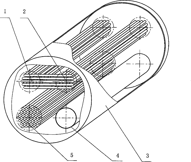
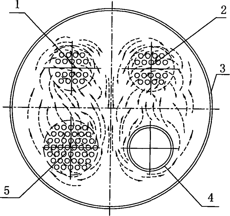
[0025] Example 1, such as Figure 4 As shown, in a large cylinder 3 with a length of 2.65 meters and a diameter of 1.22 meters, on a cross section perpendicular to the axis with the axis as the origin, a flow channel is respectively set in four quadrants divided by vertical orthogonal lines , and the two upper and lower flow channels are connected at one end of the large cylinder, and the openings at the other end are the input port and the output port respectively. The heating gas is sent out of the flow channel 2, and the gas to be heated is natural gas. The two lower flow channels are heating gas flow channels, and the lower heating gas is sent into the flow channel 4 as a pipe structure, and the burning of natural gas produces high-temperature flue gas, and the heated gas is sent into the flow channel 4 for heating, commonly known as "fire tube", and the rest , including the upper two channels for conveying the heated gas and the lower channel for sending out the heated g...

Embodiment 2

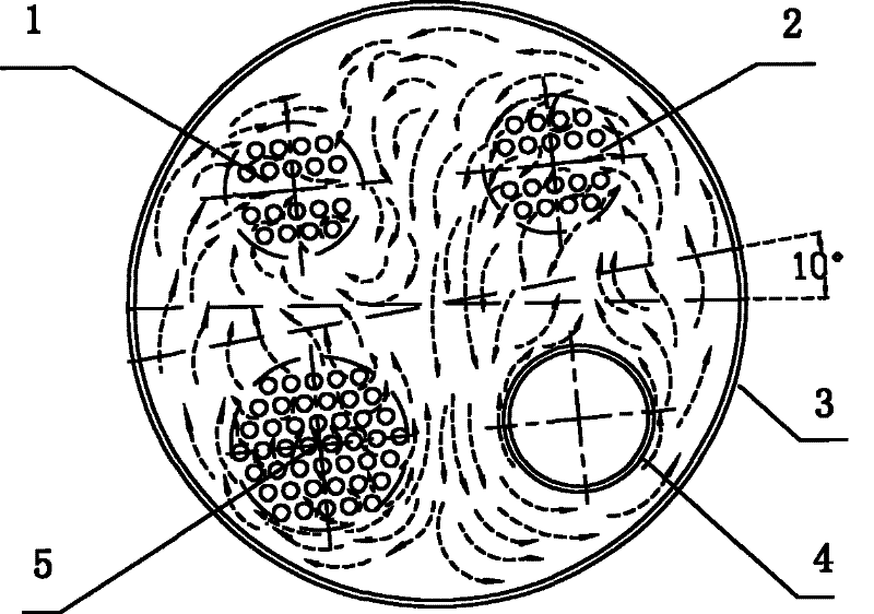
[0026] Example 2, such as image 3As shown, in a large cylinder 3 with a length of 2.65 meters and a diameter of 1.22 meters, on a cross section perpendicular to the axis with the axis as the origin, a flow channel is respectively set in four quadrants divided by vertical orthogonal lines , and the two upper and lower flow channels are connected at one end of the large cylinder, and the openings at the other end are the input port and the output port respectively, and the upper two flow channels are the input flow channel 1 and the output flow channel respectively Road 2, the gas to be heated is natural gas. The two lower flow channels are heating gas flow channels. The lower heating gas feeding flow channel 4 is a pipe structure with a diameter of 33 cm, and the combustion of natural gas produces high-temperature flue gas, which is sent into the flow channel 4 for heating by the heating gas, and the rest , including the upper two transport gas channels and the lower heating ...


PUM


Abstract

The invention relates to a device which carries out the heating and the temperature increase on natural gas during the processes of exploitation, transmission and distribution of the natural gas. The device is an improved structure of a cylindrical gas heating furnace, four quadrants of a cross section in a big cylinder (3) are respectively provided with a flow channel, the respective two flow channels of the upper part and the lower part communicate at one end of the big cylinder (3), openings at the other end are an input port and an output port respectively, the upper two are the flow channels for transmitting the gas to be heated, the lower two are the heated gas flow channels, the lower heated gas sending-in flow channel (4) is of a pipeline structure, in addition, a pipe bundle which comprises the upper two flow channels for transmitting the gas to be heated and the lower heated gas sending-out flow channel (5) is composed of a plurality of thin pipes, the interior of the big cylinder (3) is filled with middle heat-carrying media, and orthogonal lines on the cross section are rotated by an angle. The technical proposal can improve the heating efficiency by about 3 percent for the different middle heat-carrying media, the different transmitted gas and the heated gas with the different temperature differences.

Description

(1) Technical field [0001] The invention relates to a heating device for conveying gas, in particular to a device for heating and raising the temperature of natural gas in the process of natural gas exploitation, transmission and distribution. (2) Background technology [0002] As we all know, natural gas is a clean energy with high efficiency, rich resources, convenient storage and transportation, etc. It is the direction of world energy development and a powerful pillar of my country's economic development. In recent years, my country's natural gas industry is on the rise. [0003] During the extraction and long-distance transportation of natural gas, it is necessary to heat and prevent freezing of high-pressure natural gas with a large flow rate in order to achieve good transmission and distribution effects. Another example is that gas-fired power plants often need to depressurize when burning natural gas. When the pressure drop is large and the temperature drop of natura...

Claims


Application Information

Patent Timeline
Patent Type & Authority Patents(China)
IPC IPC(8): F24H7/02F24H3/08
Inventor 严平曹伟武郭韵钱尚源
Owner SHANGHAI UNIV OF ENG SCI
Why Eureka
Try Eureka