Sander for concrete powder

A concrete and grinding machine technology, which is applied in the field of grinding devices, can solve the problems of low grinding efficiency, low grinding accuracy, and inability to produce powder, etc., and achieves high grinding efficiency, convenient operation, and rapid sample preparation.

Inactive Publication Date: 2012-05-30
QINGDAO TECHNOLOGICAL UNIVERSITY
View PDF1 Cites 3 Cited by
  • Summary
  • Abstract
  • Description
  • Claims
  • Application Information

AI Technical Summary

Problems solved by technology

[0004] The existing technology generally adopts the method of crushing the concrete and then grinding it. The efficiency of the grinding method is very low, and the powder cannot be accurately prepared layer by layer from the surface of the concrete.
There are also mechanical grinding, such as the Chinese patent disclosed on March 12, 2008, the publication number is CN101138745A, which discloses a high-end turbulent vibration grinding machine, its rotating drive motor is connected with a geared motor, and the geared machine is coupled with a universal drive The drive sprocket is connected to the universal transmission coupling, the drive chain is provided on the drive sprocket, the drive chain is connected with the drive sprocket, the drive sprocket is connected to the hollow shaft, the hollow shaft is connected to the bearing seat, and the bearing The seat is erected on the support, and the hollow shaft is also connected with a rotating cylinder. The rotating cylinder is provided with a manhole, and the machine frame is arranged on the support platform. Driven by a coupling and an exciting motor, this device can grind and refine materials, but its structure is complex, its cost is high, and its grinding accuracy is not high

Method used


Image

  • Sander for concrete powder
  • Sander for concrete powder
  • Sander for concrete powder

Examples


Embodiment Construction

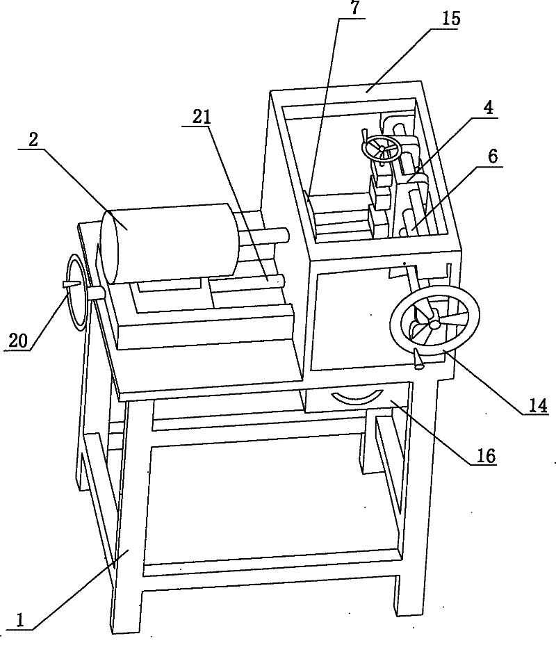
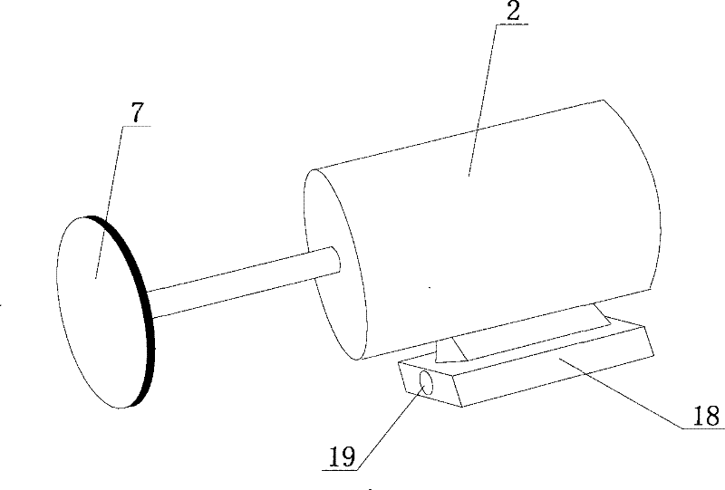
[0015] The grinding device comprises a support 1, on which a motor 2 is arranged, and a grinding sheet 7 is fixedly connected to the rotating shaft of the motor 2, and a test sample holding device 4 is arranged on the opposite side of the grinding sheet 7.

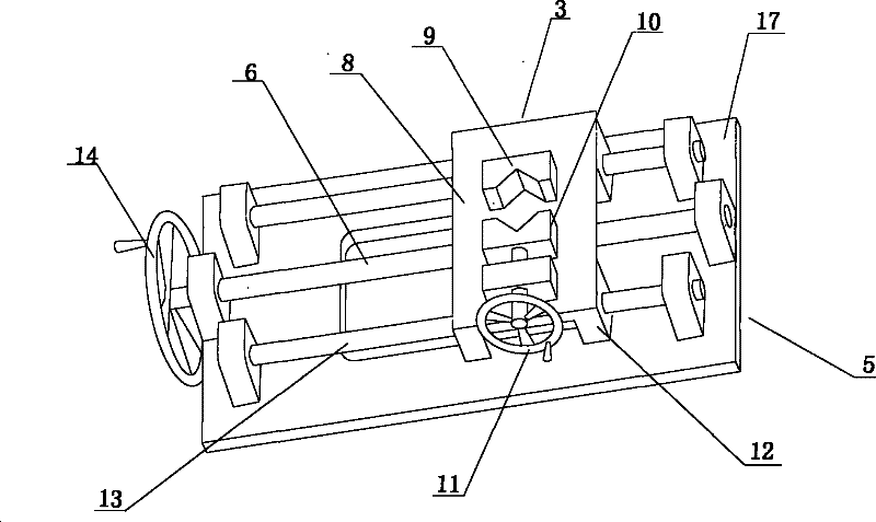
[0016] The clamping device 4 includes a clamping pliers 3 and a transmission mechanism 5 , the clamping pliers 3 are arranged on the transmission mechanism 5 and can slide along the transmission mechanism 5 . Clamping clamp 3 comprises clamping clamp support 8, and one side of clamping clamp support 8 is provided with guide rail frame 12, and the other side of clamping clamp support 8 is provided with fixed clamp 9, and the position relative to fixed clamp 9 is provided with movable clamp 10, The movable clamp 10 is connected with the clamping clamp handle 11, and the clamping clamp handle 11 drives the movable clamp 10 to move, and the distance between the fixed clamp 9 and the movable clamp 10 can be adjusted. Both the f...


PUM


Abstract

The invention relates to a grinding device, in particular to a grinder for concrete powder, including a bracket. A motor is arranged on the bracket. A grinding piece is fixedly connected with a rotating shaft of the motor. A test sample holding device is arranged opposite to the grinding piece. The holding device includes a holding clamp and a driving mechanism. The holding clamp includes a holding clamp support. One side of the holding clamp support is provided with a guide rail support, and the other side of the holding clamp support is provided with a fixing clamp. A movable clamp is arranged at a position opposite to the fixing clamp. The movable is connected to a holding clamp handle. The driving mechanism includes a base provided with a guide rail and a first manual rocking handle. The first manual rocking handle is connected to the holding clamp support through a first driving screw rod. The grinding piece, the holding clamp and the driving mechanism are all arranged in a closed tank body. A motor fixing support is arranged below the motor and is provided with through holes. A second driving screw rod is connected to a second manual rocking handle through the through holes. The second manual rocking handle is rotated to drive the motor to slide. The grinding device has the advantages of convenient operation, and higher precision of the prepared sample powder.

Description

technical field [0001] The invention relates to a grinding device, in particular to a grinding machine with a container for crushed materials. Background technique [0002] Concrete is the most commonly used building material in modern human production and life. As a multi-phase heterogeneous material, it has a porous structure from a microscopic point of view, and media such as water, air, and ions penetrate into concrete through these pores. Although the durability of concrete includes many contents, and these contents are affected by many factors, and the mechanism of action is complicated, but the common point is that they are all related to the mass transfer capacity of concrete. Most of the corrosion of concrete materials occurs under the condition of intrusion of water and harmful ions, and the durability of concrete is closely related to its permeability. It is generally believed that the lower the permeability of concrete, the more difficult it is for water and cor...

Claims


Application Information

Patent Timeline
Patent Type & Authority Patents(China)
IPC IPC(8): B02C7/11G01N1/28B02C7/06
Inventor 赵铁军范宏曹卫群王鹏刚
Owner QINGDAO TECHNOLOGICAL UNIVERSITY
Why Eureka
Try Eureka