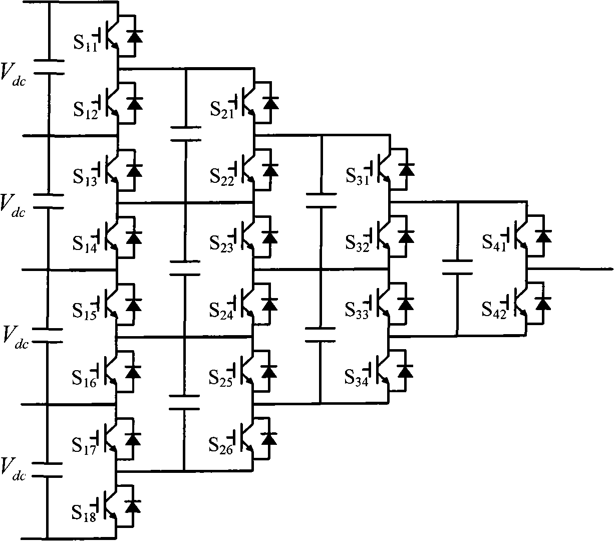
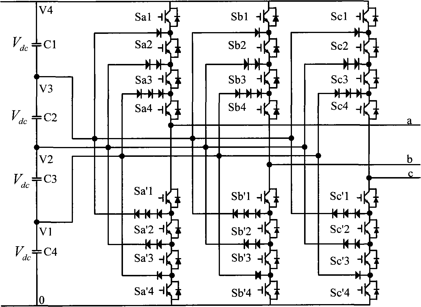
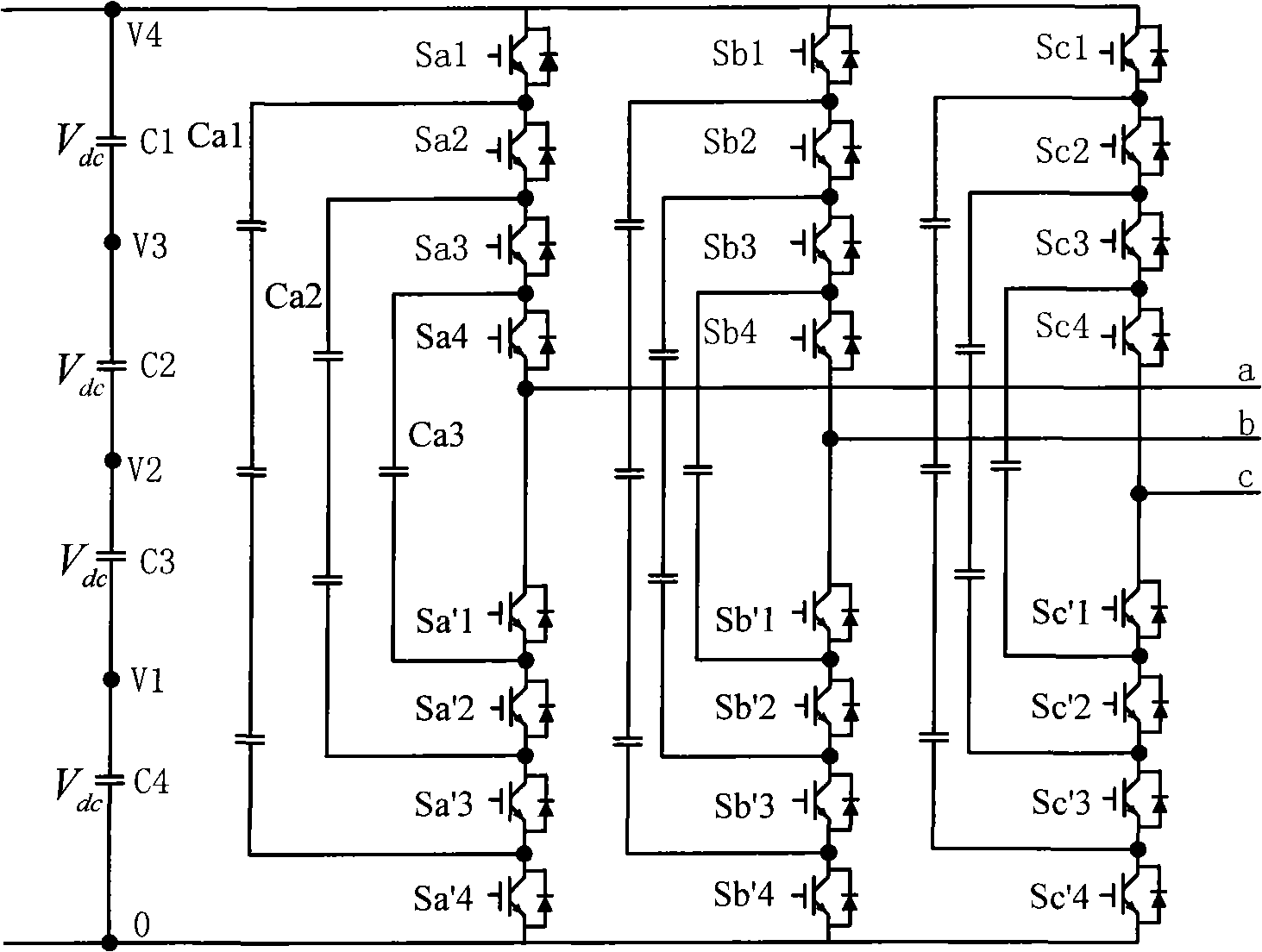
Single-phase circuit topology structure for clamp multi-level converter
A topology, single-phase circuit technology, applied in the direction of converting AC power input to DC power output, electrical components, output power conversion devices, etc., can solve the problem of high requirements for clamping capacitor withstand voltage, large number, and rising converter costs. And other issues
- Summary
- Abstract
- Description
- Claims
- Application Information
AI Technical Summary
Problems solved by technology
Method used
Image
Examples
Embodiment Construction
[0085] exist Figure 5 The single-phase topology includes 10 IGBT switching devices, 4 clamping diodes and a clamping capacitor. where S 1 with S 1 , S 2 with S 2 , S 3 with S 3 , S 4 with S4 , S 5 with S 5 are complementary switches respectively.
[0086] exist Image 6 The single-phase topology also includes 10 IGBT switching devices and a clamping capacitor, with Figure 5 Compared with the topology, 4 clamping diodes are saved. where S' 1 with S′ 1 , S' 2 with S′ 2 , S' 3 with S′ 3 , S' 4 with S′ 4 , S' 5 with S′ 5 are complementary switches respectively.
[0087] for Figure 5 For single-phase topology, when the output v o = 4V dc When the S 1 , S 2 , S 3 , S 4 , S 5 , the switching states of the rest of the switching tubes can be determined by the complementary relationship, that is, off S 1 , S 2 , S 3 , S 4 , S 5 . If the current flows from the inverter to the load, the current passes through the switch tube S 1 , S ...
PUM
 Abstract
Description
Claims
Application Information
 - R&D Engineer
- R&D Manager
- IP Professional
- Industry Leading Data Capabilities
- Powerful AI technology
- Patent DNA Extraction
Browse by: Latest US Patents, China's latest patents, Technical Efficacy Thesaurus, Application Domain, Technology Topic, Popular Technical Reports.
© 2024 PatSnap. All rights reserved.Legal|Privacy policy|Modern Slavery Act Transparency Statement|Sitemap|About US| Contact US: help@patsnap.com


