Multilevel inverter using cascade configuration and control method thereof

A technology of multi-level inverters and inverters, applied in the direction of AC motor control, control system, power factor control, etc., can solve problems such as unit problems, impossible drive of multi-level inverters, burnout, etc.

Active Publication Date: 2008-09-10
LSIS CO LTD
View PDF0 Cites 28 Cited by
  • Summary
  • Abstract
  • Description
  • Claims
  • Application Information

AI Technical Summary

Problems solved by technology

Especially for small loads, if the difference in power factor is not compensated, the regenerative voltage is concentrated to a specific (power) unit, which will cause problems or burn out of the corresponding unit, resulting in a multi-level power supply using a cascaded structure Inverter driving becomes impossible

Method used


Image

  • Multilevel inverter using cascade configuration and control method thereof
  • Multilevel inverter using cascade configuration and control method thereof
  • Multilevel inverter using cascade configuration and control method thereof

Examples


Embodiment Construction

[0020] Through the following description of the preferred embodiments of the present invention and with reference to the accompanying drawings, the objects of the present invention and the structures and operational effects adopted to achieve these objects can be more clearly understood.

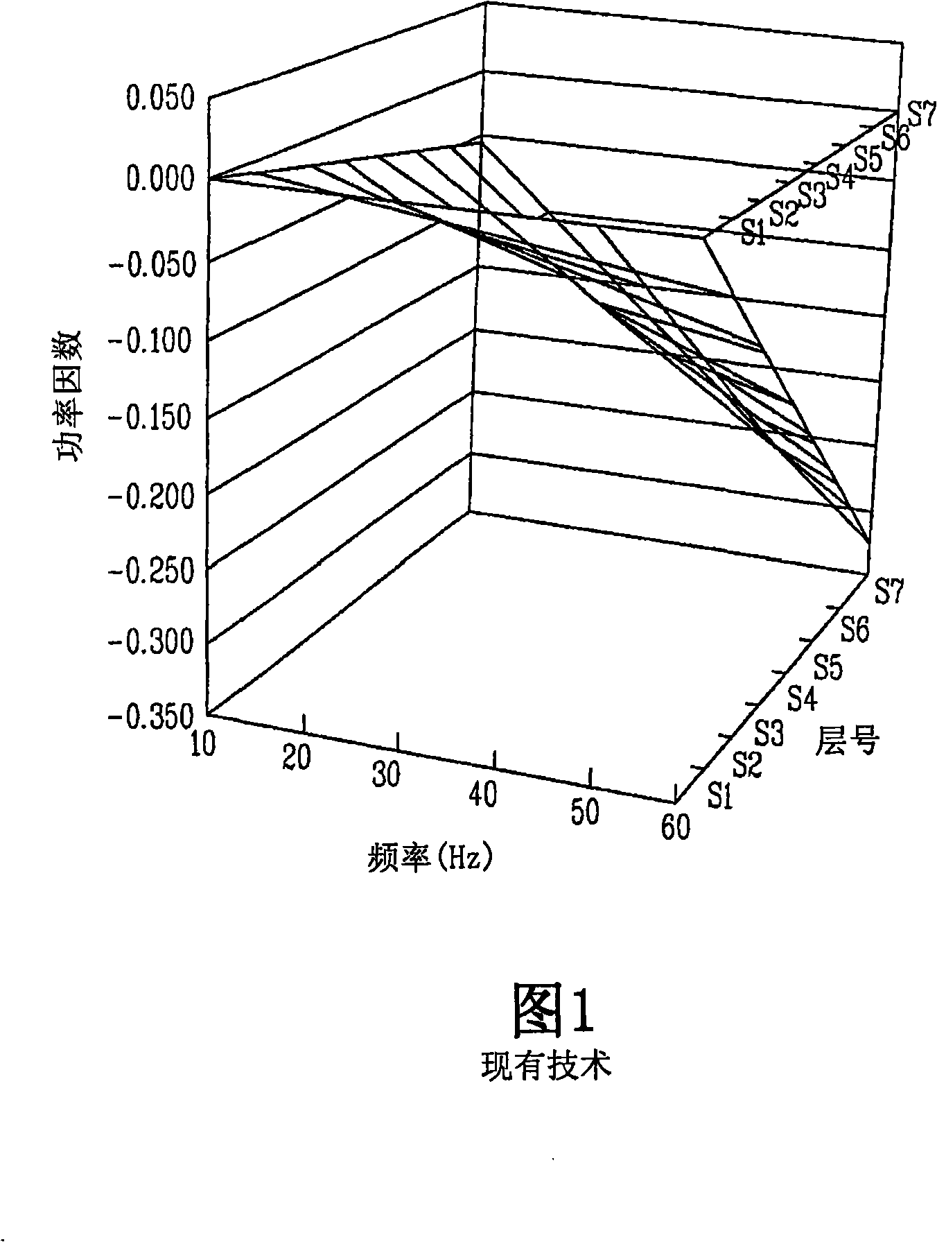
[0021] First of all, Figure 1 shows the relationship between output frequency, layer number of the power unit and power factor. This relationship shows that the power factor varies with output frequency and the Varies depending on the layer number.

[0022] As shown in Figure 1, it can be seen that when the output frequency becomes higher, the power factor of the power unit decreases. It can also be seen that for each phase of the three-phase AC (alternating current), the power factor decreases according to the layer number of the power units connected in series, that is, when the layer number (ie connection order) is further away from the input power source.

[0023] On the other hand, ref...


PUM


Abstract

A multilevel inverter using a cascade configuration with a device for equally controlling a power factor for each unit cell includes: a master controller, a plurality of power cells connected in series for each of three AC (Alternating Current) phases, a phase shift transformer for supplying a power cell input voltage, a CAN (Controller Area Network) communication network to provide a communication path between the master controller and each power cell, and cell controllers to control output voltages and output frequencies of the respective power cells according to a voltage command and a frequency command from the master controller, each cell controller having a pulse width modulator to generate a pulse width modulation control signal of a variable voltage and a variable frequency to the connected corresponding power cell, wherein each cell controller is configured to calculate a phase difference value of the corresponding power cell according to a preset total number of connected power cells and the floor number (i.e., the serial connection sequence) of the corresponding power cell to thereafter phase-shift a chopping wave by the calculated phase difference value, thereby compensating for the phase differences between each power cell.

Description

technical field [0001] The present invention relates to a high-voltage inverter, and more particularly, to a multi-level inverter using a cascade structure and a control method thereof, the inverter having means for equally controlling the power factors of a plurality of power units. Background technique [0002] Generally, a multi-level inverter using a cascade structure is a multi-level topology of high-voltage, large-capacity inverters, in which several single-phase inverters (hereinafter referred to as power units) are connected in series for three-phase currents. Each phase, therefore high voltages can be obtained using low voltage power semiconductor switches in the power cells. [0003] In this way, by connecting a plurality of single-phase power cells in series to each AC (alternating current) phase, a multi-level inverter employing a cascade structure can obtain high voltages using semiconductor switches. [0004] Also, the multilevel inverter adopting the cascade ...

Claims


Application Information

Patent Timeline
Patent Type & Authority Applications(China)
IPC IPC(8): H02M7/48H02M7/5387
CPCH02P23/0081H02M7/49H02P27/08H02P27/14H02P23/26H02M1/0003H03F1/22H02M7/155
Inventor 张汉根
Owner LSIS CO LTD
Why Eureka
Try Eureka