Sawmill grip feed mechanism
A technology for clamping and feeding wood sawing machines, which is applied to sawing components, sawing equipment, wood processing equipment, etc., can solve problems such as danger, sliding, and loosening, and achieve reduced labor intensity, high time accuracy, and not easy to loosen Effect
- Summary
- Abstract
- Description
- Claims
- Application Information
AI Technical Summary
Problems solved by technology
Method used
Image
Examples
Embodiment 1
[0037] What this embodiment provides is a kind of technical scheme of above-mentioned guiding structure:
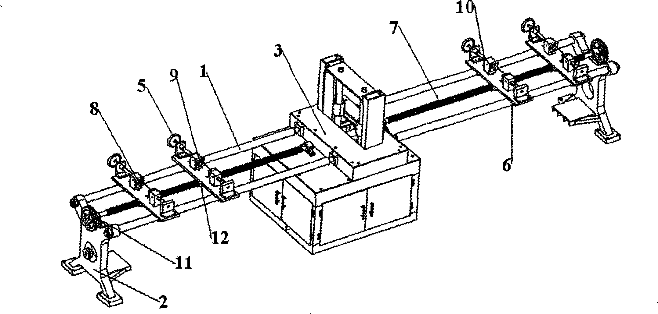
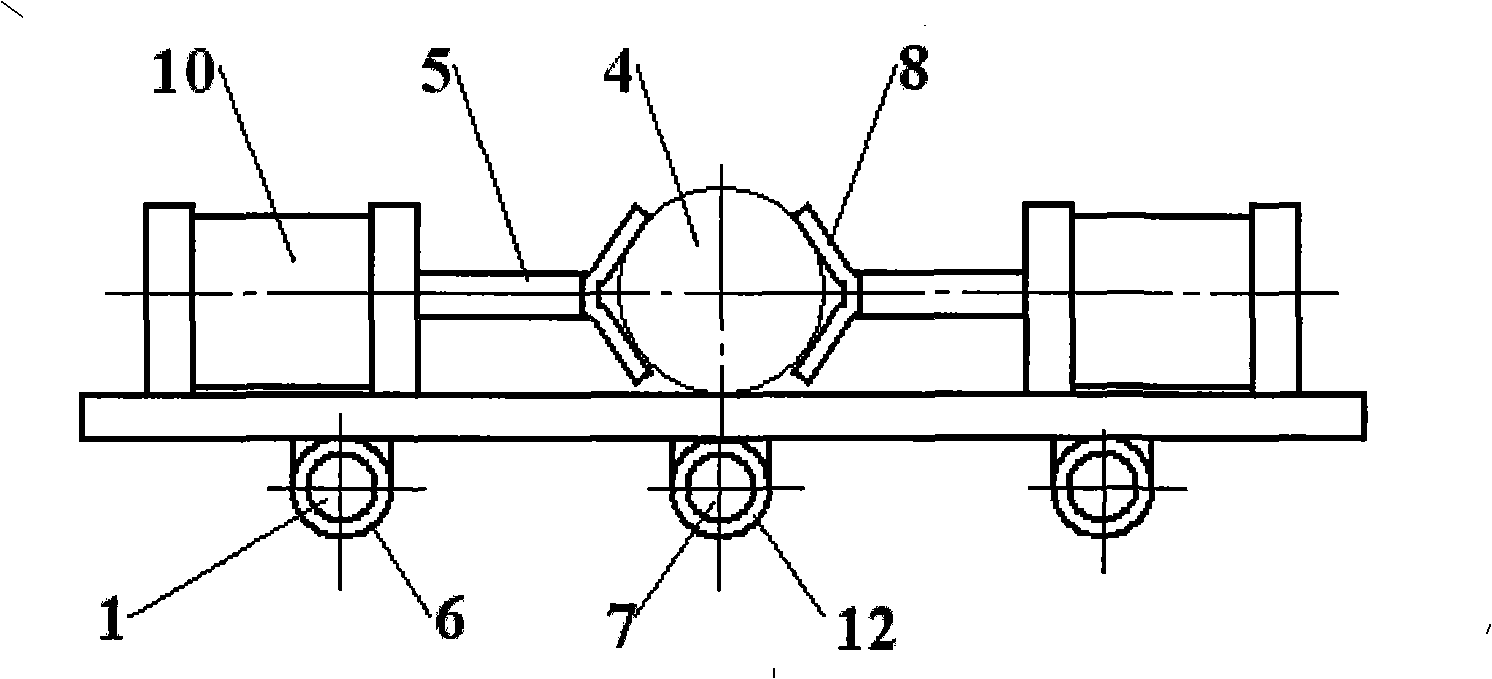
[0038] Such as figure 2 As shown, the guide structure is as follows: two parallel guide rods 1 are provided, one end is installed on the frame 2, and the other end is installed on the main machine 3 on which the saw blade moves on the sawmill. The wood clamping device 5 for clamping and feeding the wood 4, the wood clamping device 5 is set on the guide rod 1 through the guide sleeve 6, and the driving screw 7 parallel to the guide rod 1 is set, and the driving screw 7 Driven by a feed motor through a reduction mechanism 11, the wood clamping device 5 is matched with it through a nut 12.
[0039] When the wood is fed, the feed motor rotates forward, through the belt transmission mechanism, the screw rod 7 is driven to rotate, and the rotation of the screw rod 7 drives the nut 12 to make a linear motion, and drives the processed wood 4 through the wood clamping device 5 ...
Embodiment 2
[0042] What this embodiment provides is another technical solution of the above-mentioned guiding structure, that is, a technical solution using a guide rail structure:
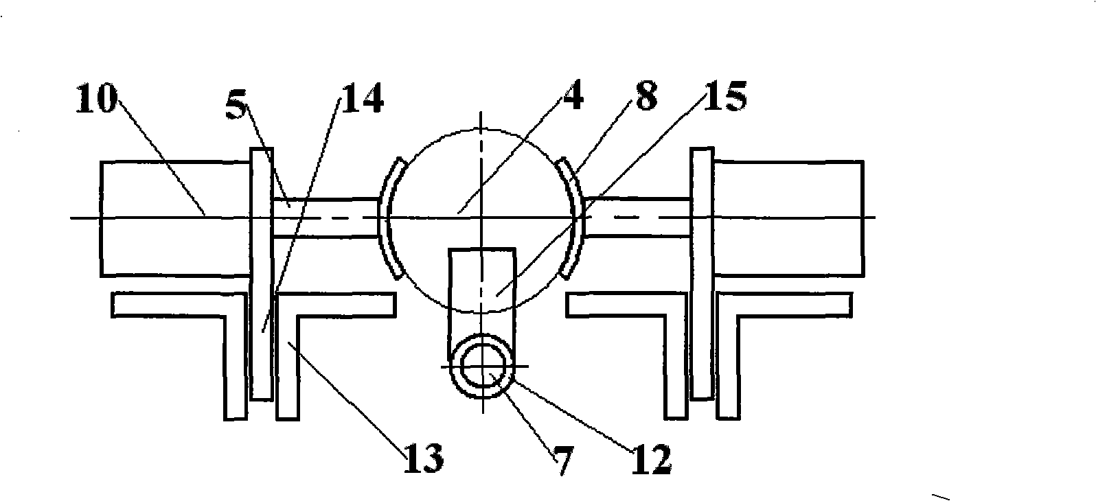
[0043] Such as image 3 As shown, the described guide structure is two parallel guide rail structures, and the described timber clamping device 5 is installed on the guide groove 13 through the slide plate 14, and the described slide plate 14 is the bottom plate of the timber clamping device 5. The driving screw 7 parallel to the guide groove 13 is driven by the feed motor through the reduction mechanism 11 . The slide plate 14 is inserted into the guide groove 13, and is clearance fit to ensure that it can slide freely.
[0044] But this wood clamping device 5 is not directly driven by the driving screw 7, and the driving structure is to cover the nut 12 on the driving screw 7, and the nut 12 is provided with a nut pushing block 15 fastened thereto, which is pressed against the processed The rear end of ti...
Embodiment 3
[0047] This embodiment provides a technical solution of a parallel guide rail structure different from that of Embodiment 2:
[0048] Such as Figure 4As shown, the described timber clamping device 5 is installed on the guide rail 16 through the slide plate 14, and the described slide plate 14 is the bottom plate of the timber clamping device 5, and is an integral structure, and the driving screw rod 7 parallel to the guide rail 16 is provided. , the drive screw 7 is driven by a feed motor through a reduction mechanism 11 .
[0049] There is clearance fit between the guide rail 16 and the slide plate 14 to ensure that it can slide easily and freely.
[0050] The way of feeding and retreating of its timber clamping device 5 can be the same as that of the first embodiment, or the same as that of the second embodiment.
PUM
 Abstract
Description
Claims
Application Information
 - R&D
- Intellectual Property
- Life Sciences
- Materials
- Tech Scout
- Unparalleled Data Quality
- Higher Quality Content
- 60% Fewer Hallucinations
Browse by: Latest US Patents, China's latest patents, Technical Efficacy Thesaurus, Application Domain, Technology Topic, Popular Technical Reports.
© 2025 PatSnap. All rights reserved.Legal|Privacy policy|Modern Slavery Act Transparency Statement|Sitemap|About US| Contact US: help@patsnap.com


