
Numerically-controlled cam grinder

A technology of cam grinder and bed, which is applied in the field of CNC cam grinder, can solve the problems of product qualification rate drop, low efficiency, complex manufacturing, etc., and achieve the effect of reducing the intermediate process of machine operation, improving production efficiency, and reducing the defective rate

Inactive Publication Date: 2008-09-10
王敏其
View PDF0 Cites 20 Cited by
  • Summary
  • Abstract
  • Description
  • Claims
  • Application Information

AI Technical Summary

Problems solved by technology

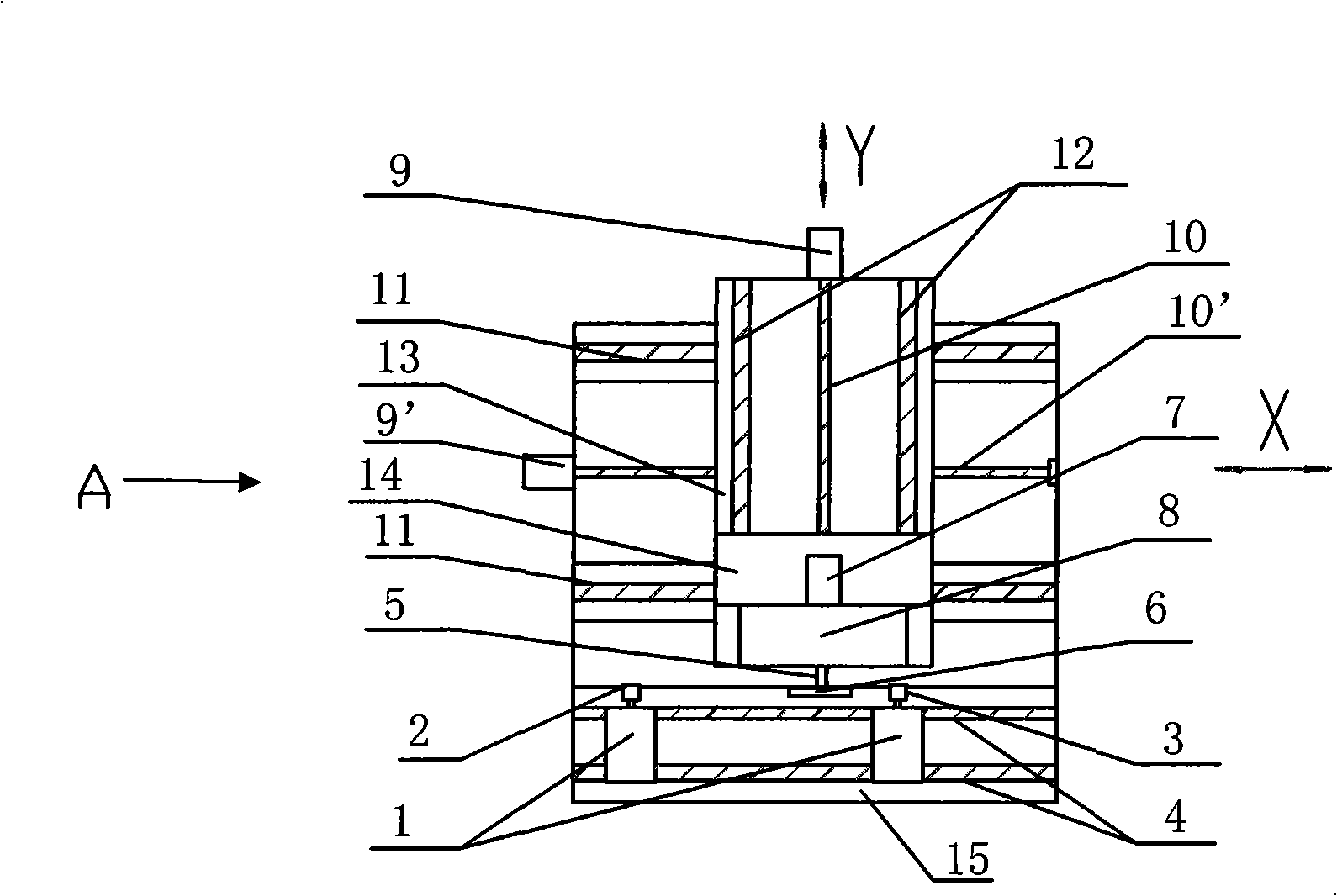
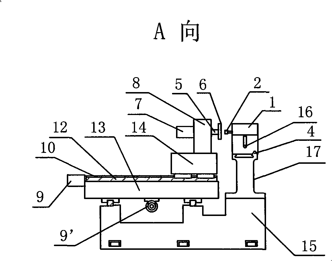
[0002] At present, our country is using self-made profiling method or manual grinding to process workpieces. The quality of workpieces is guaranteed by manual work experience to control the high-speed rotating grinding wheel or control the feed size and angle of the workpiece; When the workpiece is an irregular curved surface, its manufacturing is complicated, the pollution is large, the cycle is long, and the efficiency is low. Not only can it not meet the market demand in time, but also the labor intensity of the workers is high; especially like the cam processed by the profiling method, due to its synchronization and Poor precision directly results in high noise, high vibration, and low speed of the textile machine, and also affects the quality and output of fabric products; another traditional problem is: only one type of grinding wheel is installed on a machine, and it must be considered at the same time When processing margin and efficiency, it is often necessary to use two machines equipped with grinding wheels of different particle sizes at the same time, that is, the two problems of efficiency and surface accuracy cannot be solved on the same machine; and when two machines are used for processing, due to Repeated positioning will cause errors, which will greatly reduce the product qualification rate

Method used


Image

  • Numerically-controlled cam grinder
  • Numerically-controlled cam grinder

Examples


Embodiment Construction

[0012] The specific embodiments of the present invention will be described in further detail below in conjunction with the accompanying drawings.

[0013] Such as figure 1 , 2 As shown, a numerically controlled cam grinding machine includes a numerically controlled table, a bed 15, a workbench 14, a grinding wheel frame 1, etc., and a fine grinding head 2 and a rough grinding head are respectively installed on the transverse track 11 of the grinding wheel frame 17 on one side of the machine tool 3, two grinding wheel holders 1, the grinding wheel holder 1 is fixed on the grinding wheel holder seat 17 through positioning pins, and the position of the grinding wheel holder can be adjusted on the track as required, the grinding wheel holder seat is fixed on the machine tool, and the workbench is opposite to the grinding wheel holder seat Standing, and a horizontal sliding table is arranged under the workbench, on which there is a longitudinal guide rail matched with the workbenc...


PUM


Abstract

The invention provides a digital controlled cam grinder which comprises a digital control platform, a lathe bed, a working table, a grinding carriage etc., and the grinding carriage is fixed on the lathe bed; one side of a machine tool is provided with at least two grinding carriages which are respectively provided with a fine grinding head and a coarse grinding head; a lateral slipway is arranged under the working table, a vertical guide rail patched with the working table is arranged above the working table, the lower part of the working table is patched with the lathe bed by a lateral guide rail; two servo motors are respectively connected with the working table and the lateral slipway by a screw rod, the vertical and lateral movements of the two servo motors are driven and controlled by an operating floor. The invention greatly improves the working efficiency and assures that the feeding size and angle of the quality of workpieces are finished by the self body of digital controlled grinder, and less human factors lead the quality of the products to improve and the pollution is reduced; the processing of the digital controlled grinder is realized only by means of x and y axial rails, and the digital cam controlled grinder has the advantages of simple structure, convenient operation, good stability, low add noises and low price etc.

Description

technical field [0001] The invention belongs to the field of mechanical manufacturing, in particular to a numerically controlled cam grinder Background technique [0002] At present, our country is using self-made profiling method or manual grinding to process workpieces. The quality of workpieces is guaranteed by manual work experience to control the high-speed rotating grinding wheel or control the feed size and angle of the workpiece; When the workpiece is an irregular curved surface, its manufacturing is complicated, the pollution is large, the cycle is long, and the efficiency is low. Not only can it not meet the market demand in time, but also the labor intensity of the workers is high; especially like the cam processed by the profiling method, due to its synchronization and Poor precision directly results in high noise, high vibration, and low speed of the textile machine, and also affects the quality and output of fabric products; another traditional problem is: only...

Claims


Application Information

Patent Timeline
IPC IPC(8): B24B19/12
Inventor 王敏其赵志初
Owner 王敏其
Learn More