
Non-mechanical friction damping automatically controlling speed method and device thereof thereof

A friction damping, non-mechanical technology, used in life-saving equipment, building rescue, etc., can solve problems such as insecurity, poor stability, errors, etc., and achieve the effect of good speed control stability and fewer mechanical friction parts

Inactive Publication Date: 2008-09-03
项敏
View PDF0 Cites 14 Cited by
  • Summary
  • Abstract
  • Description
  • Claims
  • Application Information

AI Technical Summary

Problems solved by technology

In fact, this is impossible, because many of the escapees are frail old people, children and the injured. Whether it is mental state or physical strength, self-control ability or operation technology, it is difficult for a panicked escapee to survive. Operate such devices calmly and efficiently to escape
Moreover, these devices almost all rely on mechanical friction to limit the speed, because the size of the mechanical friction varies with various unstable factors such as the material of the friction parts, the surface physical properties, the pressure between the friction parts, the ambient temperature, and the humidity. Changes, poor stability, so this type of escape device that relies on mechanical friction damping to limit speed is not safe
[0004] In addition, some high-altitude operations and military activities also require practitioners to frequently descend from high altitudes. Although they have the ability to control their descent speed, they must operate and control their descent speed while performing professional work. Accidents do happen

Method used


Image

  • Non-mechanical friction damping automatically controlling speed method and device thereof thereof
  • Non-mechanical friction damping automatically controlling speed method and device thereof thereof
  • Non-mechanical friction damping automatically controlling speed method and device thereof thereof

Examples


Embodiment Construction

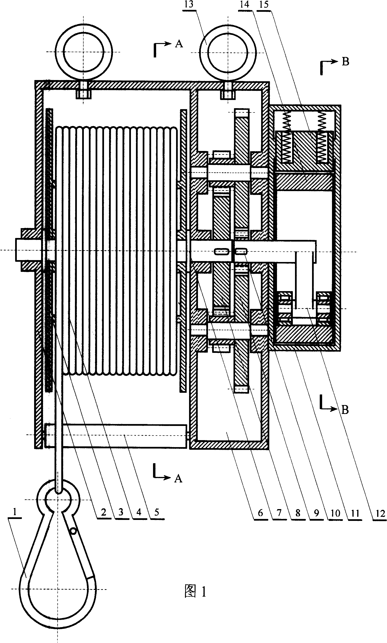
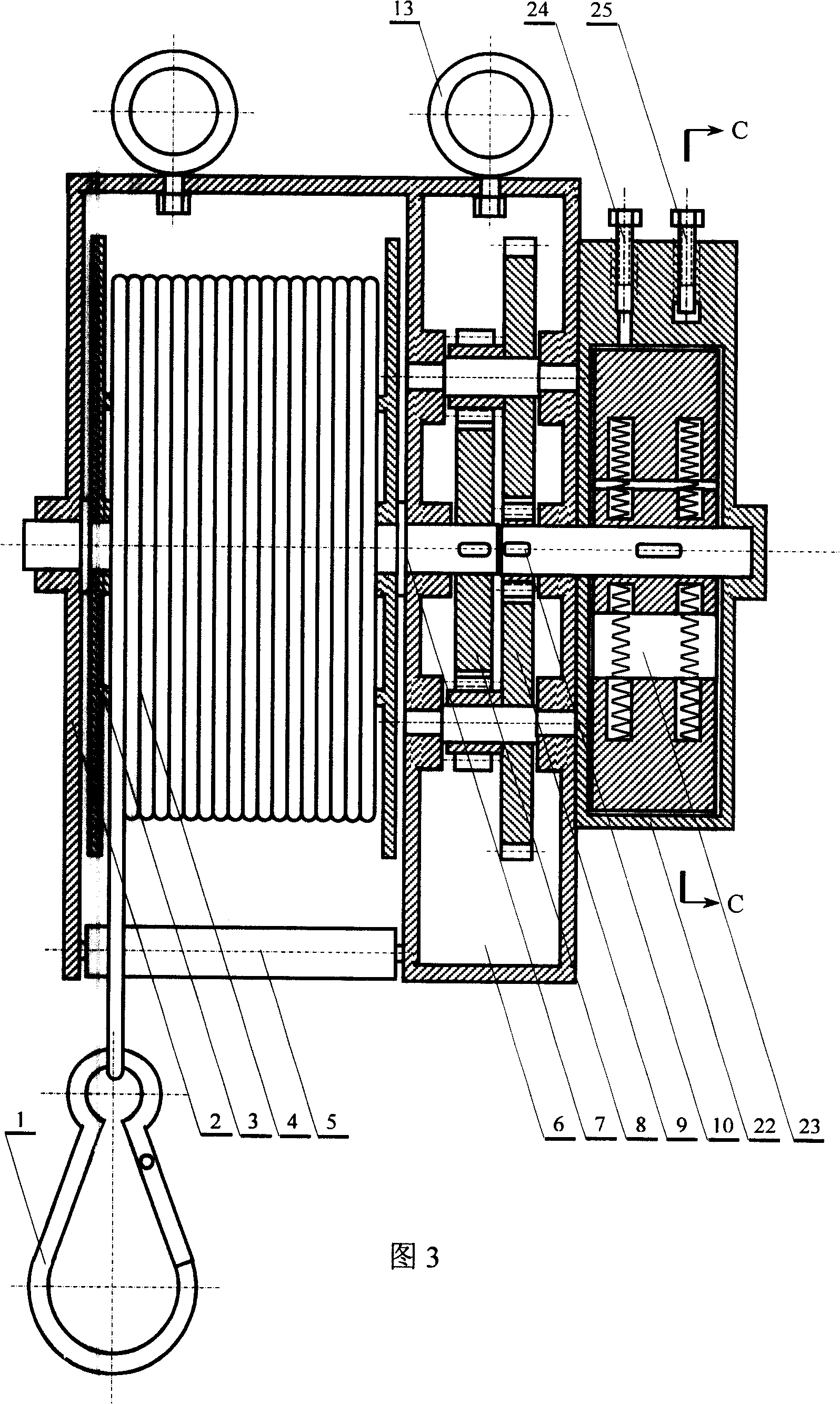
[0030] A non-mechanical friction damping automatic speed control method, that is, the fluid output end of the variable volume fluid pump is provided with a flow limiting valve as a fluid damping mechanism or the electric energy output end of a self-excited magnetic generator is electrically connected with an electrical appliance as an electromagnetic damping mechanism, and the A cable wheel with a cable wound around it is mechanically coupled.

[0031] The present invention will be illustrated by enumerating three device structures as specific embodiments for realizing the method of the present invention below.

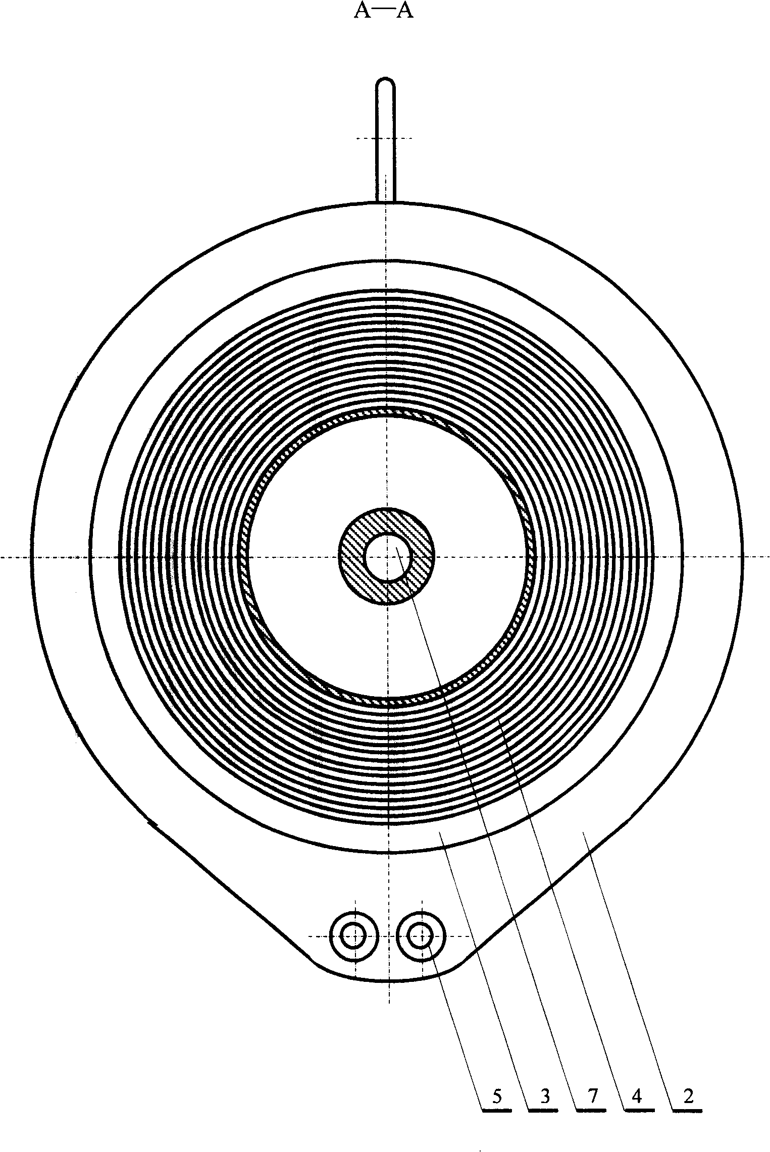
[0032] Figure 1 and figure 2 , Figure 4 Shown is a fluid damping automatic speed control device, which is mainly composed of a cable 4, a cable wheel 3, a transmission 6 and a planetary wheel fluid pump 11; the cable 4 is wound on the cable wheel 3 in an orderly manner, and is equipped with elastic One end of the cable 4 of the self-locking buckle 1 stretches out o...


PUM


Abstract

The invention discloses a non-mechanical friction damping automatic speed control method and a device thereof, the method is that: a cable wheel which is wound by a cable is mechanically linked with a fluid damping mechanism or an electromagnetic damping mechanism; the device is composed of the cable, the cable wheel, a speed change device, the fluid damping mechanism or the electromagnetic damping mechanism, the cable is serially wound on the cable wheel, a shaft of the cable wheel is linked with a power input shaft of the speed change device, a power output shaft of the speed change device is linked with a rotating shaft of the fluid damping mechanism or the electromagnetic damping mechanism, and the whole device is mounted at the fixed position by a mounting ring on an outer shell. The device can allow the speed of an escaper or a high-altitude operator during the descending process to be automatically controlled within the safe range when a high-rise building has a fire hazard, the mechanical friction parts of the device are fewer and the stability of the speed control is better.

Description

technical field [0001] The invention relates to a speed control method and a device adopting the method, in particular to a non-mechanical friction damping automatic speed control method and a device thereof. Background technique [0002] How people escape safely when a fire breaks out in a high-rise building is a problem that has not been well resolved so far. People have devised a lot of methods for escaping from high-rise buildings when a fire broke out, among which safe passage is the most commonly used method. But in fact, the flames and toxic smoke in the fire often permeate the corridors and safe passages leading to safe passages. It is difficult for panicked escapees to find safe passages in the thick smoke with extremely low visibility. This tragic case Too many to list. The most direct reaction of some trapped people is to flee to windows or balconies to call for help and try to escape. People who cannot endure the engulfing flames just jump from windows or balco...

Claims


Application Information

Patent Timeline
Patent Type & Authority Applications(China)
IPC IPC(8): A62B1/12A62B1/08
Inventor 项敏
Owner 项敏
Learn More