Releasable holding mechanism and method of use

A technology to hold the mechanism, release the connection, applied in the direction of the device used to throw or release the boat, the part of the aircraft, the special position of the vehicle, etc., can solve the problem of pollution and so on

Inactive Publication Date: 2011-09-07
孔斯贝格德沃泰克股份公司 +1
View PDF3 Cites 0 Cited by
  • Summary
  • Abstract
  • Description
  • Claims
  • Application Information

AI Technical Summary

Problems solved by technology

The establishment is also partially open for contamination

Method used


Image

  • Releasable holding mechanism and method of use
  • Releasable holding mechanism and method of use
  • Releasable holding mechanism and method of use

Examples


Embodiment Construction

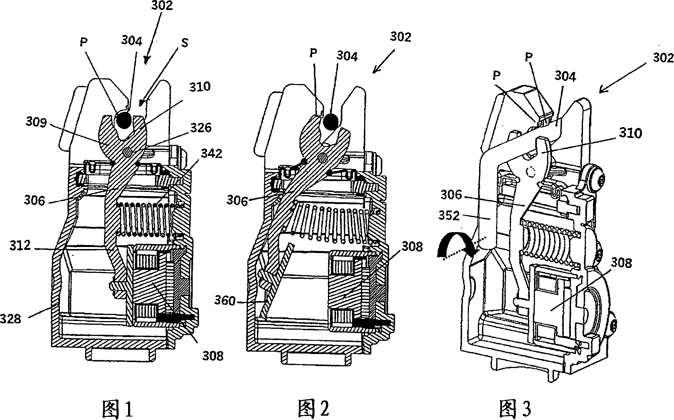
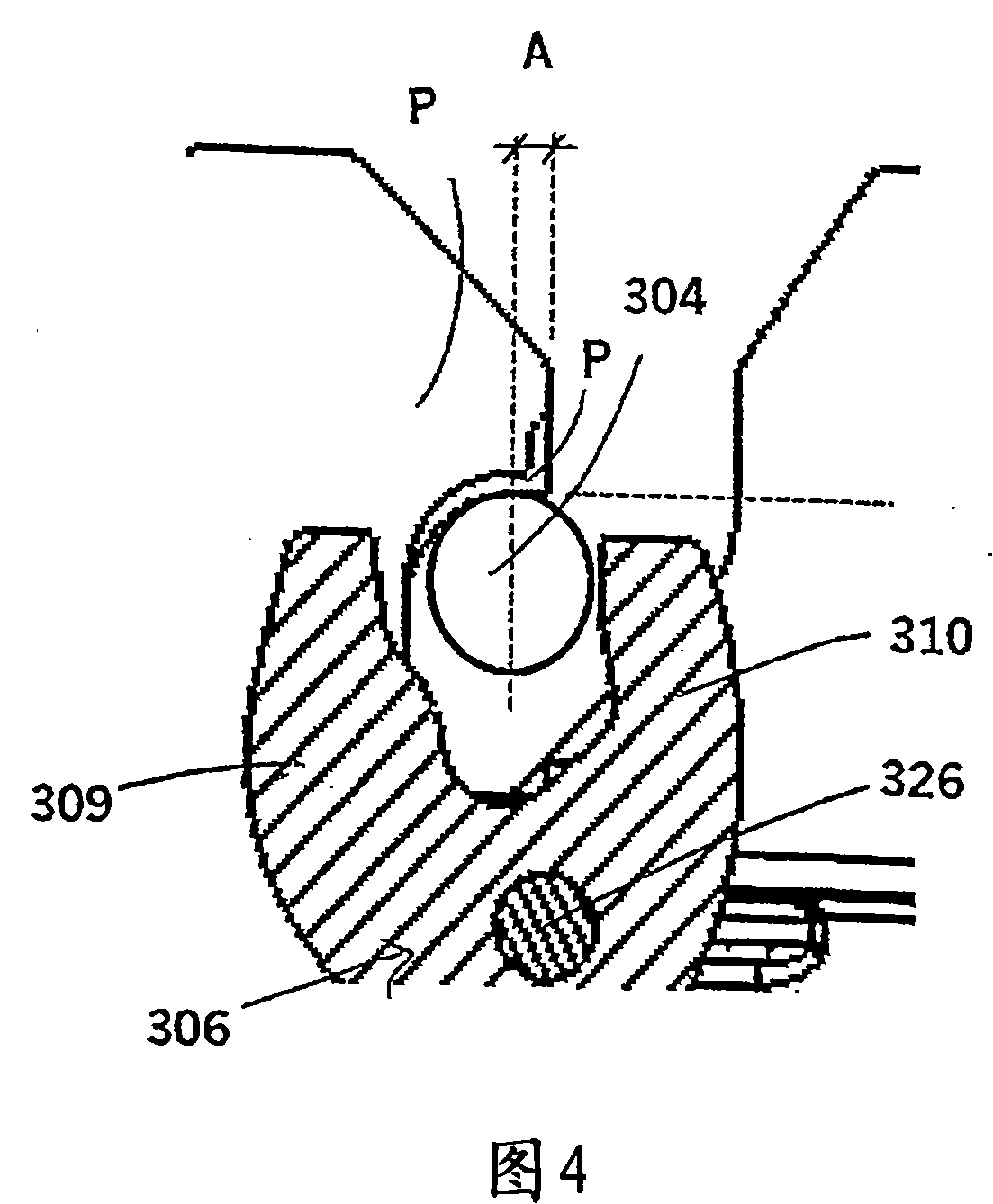
[0061] refer to Figure 1-3 , shows a first embodiment of a releasable retaining mechanism 302 for locking and releasing a connection element 304 . The releasable retaining mechanism 302 comprises a retaining means in the form of a protrusion P for retaining the connecting element 304 in the locked position and a pivotable lever 306 with at least one notch 310 for preventing the lever 306 from the locked position (eg figure 1 and 3 shown) to the unlocked position (such as figure 2 Another means is provided by magnetic attraction, for example by permanent magnets. The lever 306 is able to withstand the magnetic force of said permanent magnet; this magnetic force keeps the lever 306 in the locked position. The axis of the pivot 326 is preferably arranged on the same base element or housing as the protrusion P. The releasable retention mechanism 302 includes a combined magnet unit 308 comprising a permanent magnet and an electromagnet. The electromagnet may be connected to ...


PUM


Abstract

The present invention relates to a releasable holding mechanism which may be used to hold and release a roll bar in a roll over protection system. The roll bar is often made part of the seat structure of vehicle, or a part of the chassis of the vehicle. The releasable holding mechanism will be fastened rigidly or slightly loose to the roll bar frame, seat frame or the chassis of the vehicle. Between the roll bar and the releasable holding mechanism there will be a connection element that is rigidly or slightly loosely fastened to the roll bar. The arrangement of fastening the connection element rigidly or slightly loosely depends on the tolerances for positioning the actuator towards the roll bar. The connection element is locked or released by the releasable holding mechanism. The releasable holding mechanism is locked / -engaged when the roll bar is pushed downwards whereby the connection element is forced into the releasable holding mechanism. The releasable holding mechanism is to release the connecting element when a signal is sent to the release element of the holding mechanism. The releasable holding mechanism can be activated by one short duration pulse, for instance a pulsefrom an electronic control unit for activation of airbags in a vehicle. The system can be activated with low energy demands.

Description

technical field [0001] The present invention relates to a releasable holding mechanism with means for holding the mechanism in a locked state and a method for activating the mechanism, in particular but not limited to a roll-over protection system (ROPS), Releasable headrests, backrests, hoods for pedestrian protection and other releasable retention mechanisms for automotive applications. [0002] The invention is especially designed for ROPS, but can also be applied to other places where it is necessary to release fixed loads, such as marine safety equipment, life rafts (as a replacement for rope-cutter devices), securing and releasing cargo and release mechanisms for aviation, etc. Wait. Background technique [0003] A Roll Over Protection System (ROPS) is installed in a vehicle to protect the driver and passengers in case the vehicle rolls over. During normal driving, the tip-over bar or protective member is stored in a lower, retracted position. Only the roll bar is r...

Claims


Application Information

Patent Timeline
Patent Type & Authority Patents(China)
IPC IPC(8): B60R21/34B60N2/433B60R21/13B63B25/24B64D1/02B63B23/28B63B23/70B60N2/427
CPCB60R21/13B60R2021/135
Inventor V·L·诺吕姆B·韦斯特戈德J·厄延O·格伦利G·B·延森R·H·彼德森
Owner 孔斯贝格德沃泰克股份公司
Why Eureka
Try Eureka