
Laminated phase-difference film

A retardation film and retardation technology, applied in layered products, optics, instruments, etc., can solve the problems of poor optical uniformity and increased photoelastic coefficient of laminated films.

Inactive Publication Date: 2008-08-27
TEIJIN KASEK KK
View PDF5 Cites 2 Cited by
  • Summary
  • Abstract
  • Description
  • Claims
  • Application Information

AI Technical Summary

Problems solved by technology

In this method, although an optical film with good display quality is provided, the photoelastic coefficient of the laminated film becomes large, and a slight stress can cause a change in phase difference, which has the problem of poor optical uniformity.

Method used


Image

  • Laminated phase-difference film
  • Laminated phase-difference film

Examples


Embodiment 1

[0119] (Film A1)

[0120] A polycarbonate resin (manufactured by Teijin Chemicals Co., Ltd., AD-5503) was dissolved in methylene chloride, and cast into a film to obtain a polycarbonate resin cast film having a thickness of 35 μm. At 151° C., the film was uniaxially stretched 1.3 times in the longitudinal direction of the free end to obtain a retardation film A1 having a Re of 262 nm in light of a wavelength of 550 nm and a film thickness of 30 μm. The photoelastic coefficients of the polycarbonate resin casting film and the retardation film A1 used to prepare the retardation film A1 were measured, and it was found that they were 75×10 before and after stretching. -12 Pa -1 .

[0121] (Film B1)

[0122] Next, at 143°C, a ring-opening polymerization type polynorbornene film (manufactured by Zeon Co., Ltd., ZEONOR) with a film thickness of 170 μm was uniaxially stretched 2.0 times in the longitudinal direction of the free end to produce the wavelength of the refractive index....

Embodiment 2 and 3

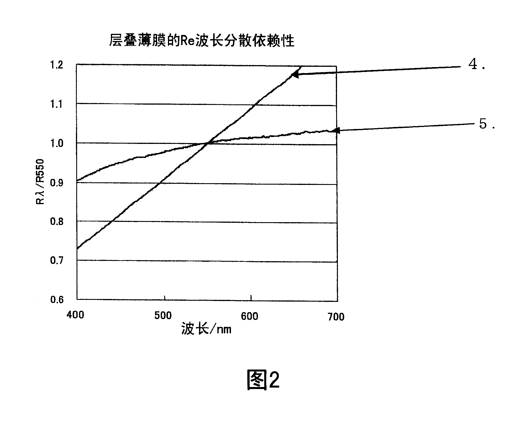
[0126] Using the retardation films shown in Table 1, a laminated retardation film was produced in the same manner as in Example 1. Table 2 shows the properties of the obtained laminated film.

Embodiment 4

[0128] (Film B4)

[0129] At 143°C, a film with a thickness of 170 μm produced by melt-extruding a copolymerized polynorbornene resin (DAICEL Chemical Industry Co., Ltd., TOPAS) was uniaxially stretched 2.0 times in the longitudinal direction of the free end to obtain Retardation film B4 with a Re of 400 nm and a film thickness of 120 μm in light with a wavelength of 550 nm. The photoelastic coefficients of the polynorbornene film used to prepare the retardation film B4 and the retardation film B4 were measured, and it was found that both before and after stretching were -7.8×10 -12 Pa -1 .

[0130] (cascade)

[0131] This retardation film B4 and the aforementioned retardation film A1 were produced in the same manner as in Example 1 to form a laminated retardation film. Table 2 shows the properties of the obtained laminated retardation film.


PUM

PropertyMeasurementUnit
photoelasticityaaaaaaaaaa

Abstract

The invention provides a laminated phase difference film with good transparency, heat resistance and mechanical property, good wavelength disperse property and small photo-elastic coefficient, and a laminated phase difference film capable of implementing good contrast and wide visible angle in a liquid crystal display. A laminated phase difference film is characterized by that the laminated phase difference film is composed of film A and film B are adhered with delay phase shafts thereof vertical to each other and meets the following formulas (1) to (4); wherein, the film A is formed by directional extension of a polymer with positive photo-elastic coefficient, while the film B is formed by directional extension of a polymer with negative photo-elastic coefficient; beta is no more than 20*10<-12>Pa<-1> (1); dA+dB is no less than 50mum but no more than 180mum (2); R(550) is no less than R(450) but no more than R(650) (4).

Description

technical field [0001] The present invention relates to a laminated retardation film which is excellent in transparency, heat resistance, mechanical properties, and optical properties and which is suitable for use in liquid crystal display devices. Background technique [0002] In a liquid crystal display, a retardation film is a birefringent film used to change the relative phase of polarized light components. In liquid crystal displays, in order to obtain sharp and fine images, it is required that the entire surface of the birefringent layer has optical uniformity, and at the same time, it is required that its optical properties will not change with changes in the environment such as temperature or humidity, and that the value of birefringence is required to be within It is suitable for the liquid crystal display device in the whole wavelength range. [0003] As retardation films, polymer films such as polyvinyl alcohol resins, triacetyl cellulose, and polycarbonate resin...

Claims


Application Information

Patent Timeline
Patent Type & Authority Applications(China)
IPC IPC(8): G02B5/30B32B7/02G02F1/13363
Inventor 浴中达矢新田英昭畠中邦夫长谷川欣治
Owner TEIJIN KASEK KK
Learn More