
Modular energy feedback type traction power set and control method

A technology of energy feedback and traction power supply, which is applied in the direction of output power conversion devices, electrical components, power lines, etc., can solve the problems of large harmonic pollution of the AC power grid, failure of energy feedback, and unfavorable light weight of vehicles, etc., to improve power supply Reliability, improved system reliability, and ease of modular design

Inactive Publication Date: 2008-08-27
BEIJING JIAOTONG UNIV +1
View PDF0 Cites 58 Cited by
  • Summary
  • Abstract
  • Description
  • Claims
  • Application Information

AI Technical Summary

Problems solved by technology

Although this kind of diode rectifier has a simple structure and low cost, it also has some inherent disadvantages: firstly, the energy when the vehicle brakes cannot be fed back to the AC grid, which will undoubtedly cause a lot of energy waste for rail vehicles that need frequent starting / braking ; Secondly, the output voltage fluctuates greatly. The starting and braking of the vehicle, as well as the fluctuation of the AC input voltage, will cause large fluctuations in the DC output voltage, which is not conducive to the reliable operation of the vehicle at full power.
The third is that the vehicle needs to be equipped with a bulky braking resistor, which is not conducive to the lightweight of the vehicle, and also brings about the problem of heat dissipation; in addition, it also causes relatively large harmonic pollution to the AC power grid
The use of PWM rectifiers can overcome many of the above defects of diode rectifiers, but the capacity of a single PWM rectifier is difficult to achieve several megawatts, and the large capacity of a single unit is not conducive to the flexible configuration of the power supply system capacity, and will also reduce the reliability of power supply

Method used


Image

  • Modular energy feedback type traction power set and control method
  • Modular energy feedback type traction power set and control method
  • Modular energy feedback type traction power set and control method

Examples


Embodiment Construction

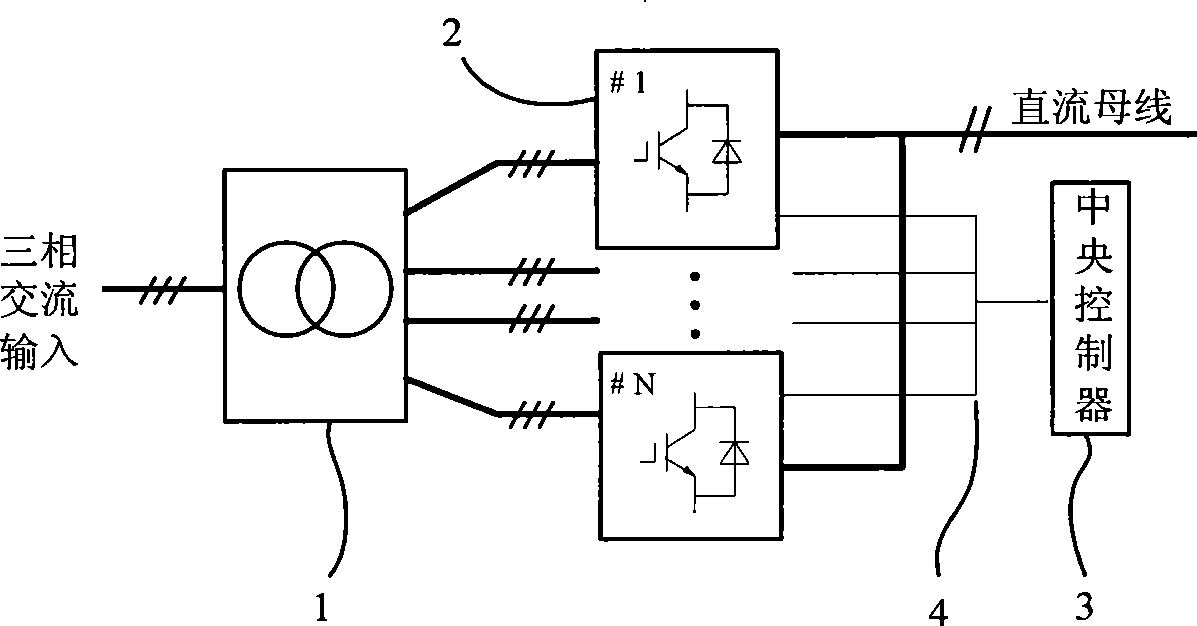
[0021] The present invention proposes a modularized energy feedback type traction power supply device, which includes:

[0022] A multi-winding transformer 1, the transformer is composed of a primary winding and a plurality of secondary windings, the primary winding is connected to the AC power grid, and a star connection is adopted, each secondary winding is connected to a PWM rectifier unit, and the connection of each secondary winding In the same way, they all adopt triangle connection;

[0023] A plurality of PWM rectifier units 2, the DC outputs of all rectifier units are connected in parallel to the DC bus as the total output of the power supply device;

[0024] A central controller 3, which is interconnected with each PWM rectifier unit through a CAN network 4.

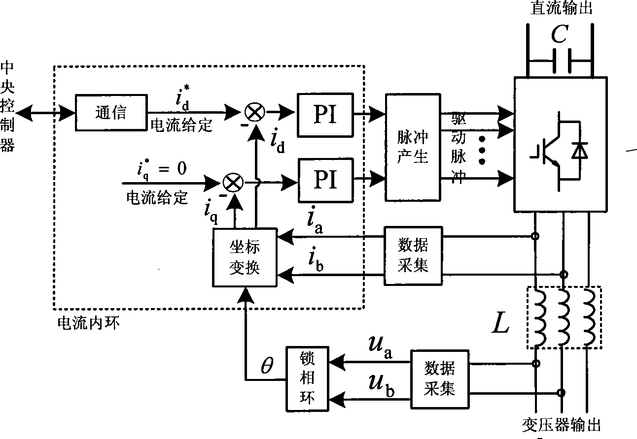
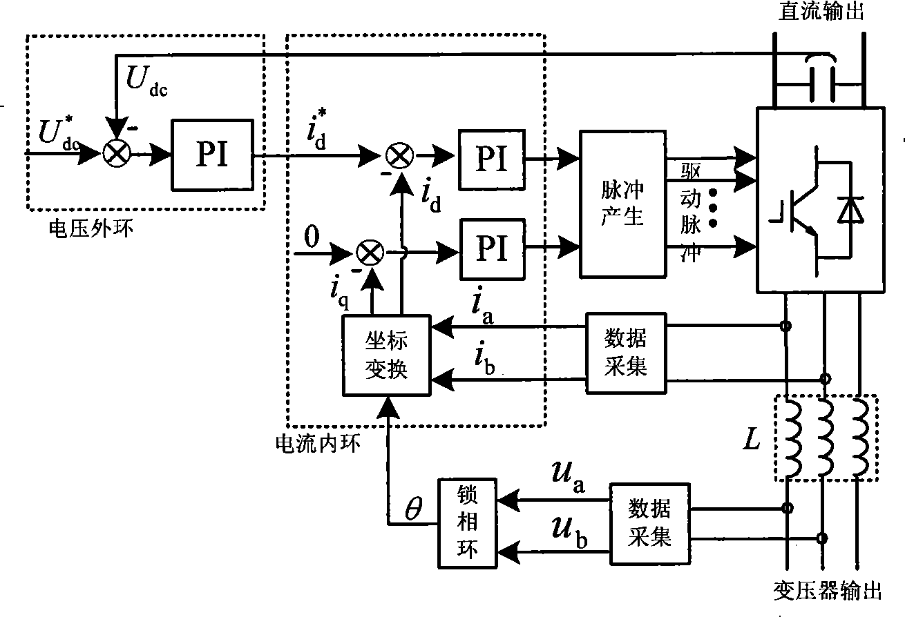
[0025] The central controller includes a DC voltage sensor and a CPU board, and the CPU board contains a digital signal processor and a CAN communication interface.

[0026] The power switch tubes in each PWM...


PUM


Abstract

The invention relates to a modularized energy feedback traction power supply device and a control method thereof, wherein, the device comprises a multi-winding transformer, a plurality of PWM rectifier units and a central controller, wherein, the multi-winding transformer is provided with a primary winding and a plurality of secondary windings, and all of the secondary windings have the same connecting mode; each secondary winding of the transformer is connected with a PWM rectifier unit; the direct-current outputs of all the PWM rectifier units are connected to a direct-current bus of the general power supply device in serials. Double closed-loop control of voltage and current is adopted; an outer loop of direct-current voltage is arranged on the central controller and an inner loop based on synchronous rotating frame is arranged on each PWM rectifier unit. The power supply device is remarkably characterized by easy modularization, large capacity, bipolar energy transmission, high power factor, small current harmonic wave and stable direct-current voltage.

Description

technical field [0001] The invention relates to a traction power supply device and a control method, in particular to a traction power supply device and a control method which adopt a plurality of PWM rectifiers connected in parallel and have an energy feedback function. Background technique [0002] The development of urban rail transit is conducive to alleviating the increasing congestion of urban traffic, improving the living environment of the city and promoting the sustainable development of the city. [0003] At present, the traction power supply devices of China's subways and light rails use traditional diode rectifiers, and the power supply voltage is mainly 750V or 1500V. Although this kind of diode rectifier has a simple structure and low cost, it also has some inherent disadvantages: firstly, the energy when the vehicle brakes cannot be fed back to the AC grid, which will undoubtedly cause a lot of energy waste for rail vehicles that need frequent starting / braking...

Claims


Application Information

Patent Timeline
IPC IPC(8): B60M3/00B60M3/06H02M7/12H02M5/10H02M1/12H02M1/42
Inventor 刘志刚贾利民赵明花卢西伟沈茂盛张钢狄威刁利军牟富强王磊李哲峰林文立梅樱罗荣娅
Owner BEIJING JIAOTONG UNIV
Learn More