Modularization exposure system

An exposure system and modular technology, applied in the field of exposure systems, can solve problems such as damage to exposure units

Active Publication Date: 2008-08-20
HANS LASER TECH IND GRP CO LTD
View PDF2 Cites 5 Cited by
  • Summary
  • Abstract
  • Description
  • Claims
  • Application Information

AI Technical Summary

Problems solved by technology

[0006] In order to solve the problem that the exposure system in the prior art cannot conveniently and quickly deal with the damage of individual exposure units in the exposure mechanism, the present invention proposes a modular exposure that can perform online detection on the exposure modules in the exposure mechanism and perform replacement repairs according to the detection results. system

Method used


Image

  • Modularization exposure system
  • Modularization exposure system
  • Modularization exposure system

Examples


Embodiment Construction

[0029] The present invention will be described in detail below in conjunction with the accompanying drawings and embodiments.

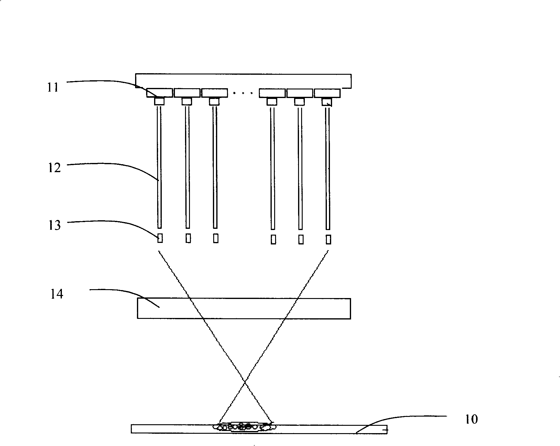
[0030] figure 1 as shown, figure 1 It is a structural schematic diagram of the first embodiment of the exposure module of the modular exposure system of the present invention. In this embodiment, the exposure structure includes a plurality of exposure modules, and each exposure module includes a light-emitting diode (Light-Emitting Diode, LED), an organic light-emitting diode (Organic Light-Emitting Diode, OLED) or a laser diode (Laser Diode, LD), etc. A light source device 11 , an optical fiber 12 and a microlens 13 . The ultraviolet, visible and infrared rays of the required band for exposure produced by the light source device 11 are guided to the exposure substrate 10 coated with a photosensitive medium material through the optical fiber 12, and are output to the optical fiber 12 by the microlens 13 arranged at the output end of the optical fibe...


PUM


Abstract

The invention relates to a modular exposure system, which comprises: an exposure mechanism which is used to expose the exposure base with a photosensitive medium layer; a transmission mechanism which is used to ensure the relative motion of the exposure base and the exposure mechanism, wherein the exposure mechanism comprises a plurality of exposure modules, and the exposure system further comprises a failure testing mechanism which is used to test the exposure module in the exposure mechanism and a replacement mechanism which is used to replace the failure exposure module or the replacement element of the failure exposure module according to the testing result of the failure testing mechanism. According to adopting the structure, the modular exposure system has the advantages of achieving the replacement modular design of the exposure mechanism of the exposure system, and guaranteeing the reliable application of the whole exposure system by utilizing the real-time on-line detection and the replacement type renovation.

Description

【Technical field】 [0001] The invention relates to an exposure system, in particular to a modular exposure system suitable for plate making and phototypesetting systems. 【Background technique】 [0002] In a computer to conventional plate (CTcP) system, scanning exposure or array exposure technology is usually used. At present, scanning exposure technology usually uses an expensive laser as a light source, and its overall exposure speed cannot be improved due to the limitation of a single light source and scanning mechanism. Array exposure technology solves the problem of slow overall exposure speed in scanning exposure technology. With the reduction of the price of light-emitting diode (LED) devices, the array exposure technology based on LED light sources has gradually received widespread attention. [0003] For example, Chinese Patent No. 95117835.0 discloses a flat-panel optical fiber scanning phototypesetting machine, in which a plurality of LEDs are used as light sourc...

Claims


Application Information

Patent Timeline
Patent Type & Authority Applications(China)
IPC IPC(8): B41B21/16B41B19/00
Inventor 高云峰孙海翔苏振庆
Owner HANS LASER TECH IND GRP CO LTD
Why Eureka
Try Eureka